
Spin riveting puncher pin

A technology of riveting punches and riveting punches, which is applied in the field of rotary riveting punches, can solve problems affecting riveting quality and low processing efficiency, and achieve the effects of good riveting quality, improved riveting efficiency, and improved riveting quality

Active Publication Date: 2018-10-19
XIAN AVIATION BRAKE TECH
View PDF8 Cites 3 Cited by
  • Summary
  • Abstract
  • Description
  • Claims
  • Application Information

AI Technical Summary

Problems solved by technology

[0014] In order to overcome the problems existing in the prior art that affect riveting quality and low processing efficiency, the present invention proposes a rotary riveting punch

Method used


Image

  • Spin riveting puncher pin
  • Spin riveting puncher pin
  • Spin riveting puncher pin

Examples


Embodiment Construction

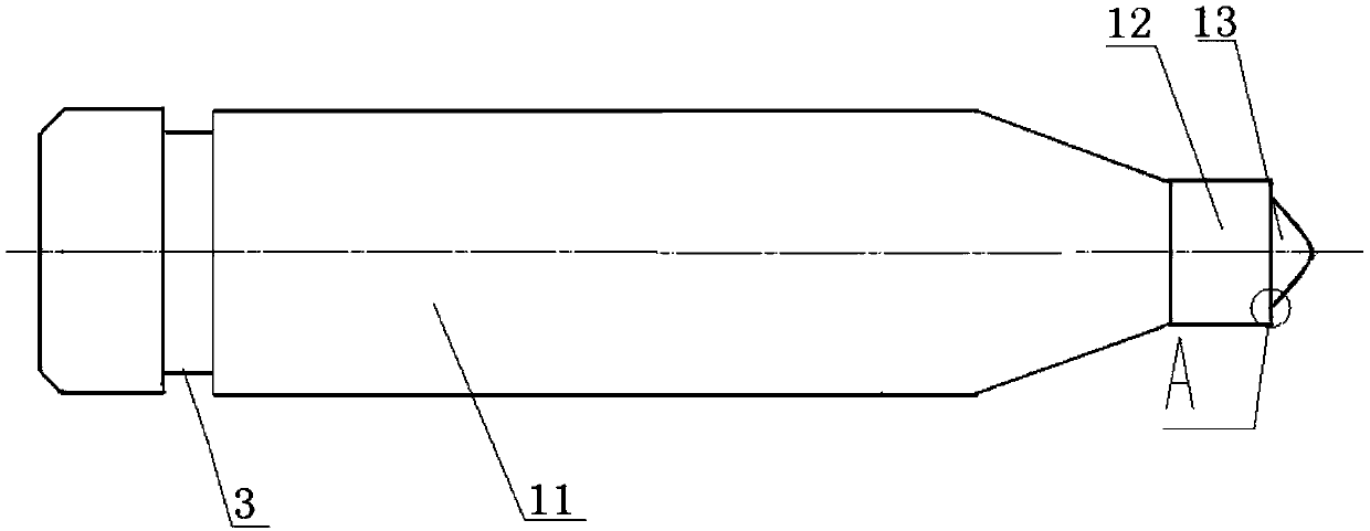
[0036] This embodiment is a spin riveting punch with a rod shape. One end of the riveting punch 9 is a connecting handle, and the other end is a riveting head, and the transition section between the connecting handle and the riveting head is a cone. The rivet head is composed of an equal-diameter section 12 and a plug 13; one end of the equal-diameter section connects with the end face of the transition section, and the center of the other end end face is an axially protruding plug. The axial length of the outer edge of the end face of the equal-diameter section is greater than the axial length of the root of the end face, so that the root of the plug forms a slope to the outer edge. The slope is the axial extrusion surface 2 of the rivet punch. The included angle between the axial extrusion surface and the space vertical surface is the axial extrusion angle α of the rivet head; the axial extrusion angle α=1°˜3°.

[0037] The plug 13 is conical, the conical surface of the co...


PUM


Abstract

The invention relates to a spin riveting puncher pin. One end is provided with a connecting handle, and the other end is provided with a spin riveting head. The spin riveting head is composed of an equal-diameter section and an ejection head, one end of the equal-diameter section is joined with the end face of a transition section, and the ejection head protruding in the axial direction is arranged in the center of the end face of the other end. The axial length of the outer edge of the end face, provided with the ejection head, of the equal-diameter section is larger than the axial length ofthe root part of the ejection head of the end face, and a slope is formed from the root part of the ejection head to the edge. The slope is an axial extrusion face of the spin riveting puncher pin. The spin riveting puncher pin is suitable for being used in a swing exhibition rivet method, key effects on the machining quality of parts and durability of the puncher pin are achieved, the riveted parts are good in consistency, and the machining efficiency and the yield are greatly improved.

Description

technical field [0001] The invention relates to the field of mechanical processing, in particular to a rotary riveting punch. Background technique [0002] Rivets are generally processed from plastic materials and are used for riveting links between parts. During the riveting process, the rivets will produce strong plastic deformation. Due to improper processing technology, the rivets will crack and the parts will be scrapped. [0003] Today, with the rapid development of industrial technology, the competition among industries has higher requirements for the quality stability and efficiency of parts processing. The traditional manual riveting process is inconvenient to operate. Generally, it needs to go through two processes of pre-punching and forming. step, the processing efficiency is low, and the consistency of the processed parts is poor, which can no longer meet the technical requirements of high-efficiency processing. [0004] In the past rivet riveting process, due ...

Claims


Application Information

Patent Timeline
Patent Type & Authority Applications(China)
IPC IPC(8): B21J15/12B21J15/36
CPCB21J15/12B21J15/36B21J15/04
Inventor 张剑利李志杰
Owner XIAN AVIATION BRAKE TECH
Learn More