Self-pressing type hole punching device and punching method

A punching device and punching technology, applied in the field of punching dies, can solve problems such as unsatisfactory punching effect and slow punching efficiency, and achieve the effects of saving labor intensity, convenient installation and maintenance, and reasonable and ingenious structure

Inactive Publication Date: 2018-10-19
陈嘉亮
View PDF5 Cites 8 Cited by
  • Summary
  • Abstract
  • Description
  • Claims
  • Application Information

AI Technical Summary

Problems solved by technology

[0002] When the plate is punched, it needs to be positioned. In the process of processing, it is necessary to use a punching tool to punch a hole at a predetermined position on the surface. The existing plate positioning device cannot form a good linkage with the punching rod, resulting in the efficiency of punching. Slow, the punching effect is not ideal, there is room for improvement

Method used


Image

  • Self-pressing type hole punching device and punching method
  • Self-pressing type hole punching device and punching method
  • Self-pressing type hole punching device and punching method

Examples


Embodiment 1

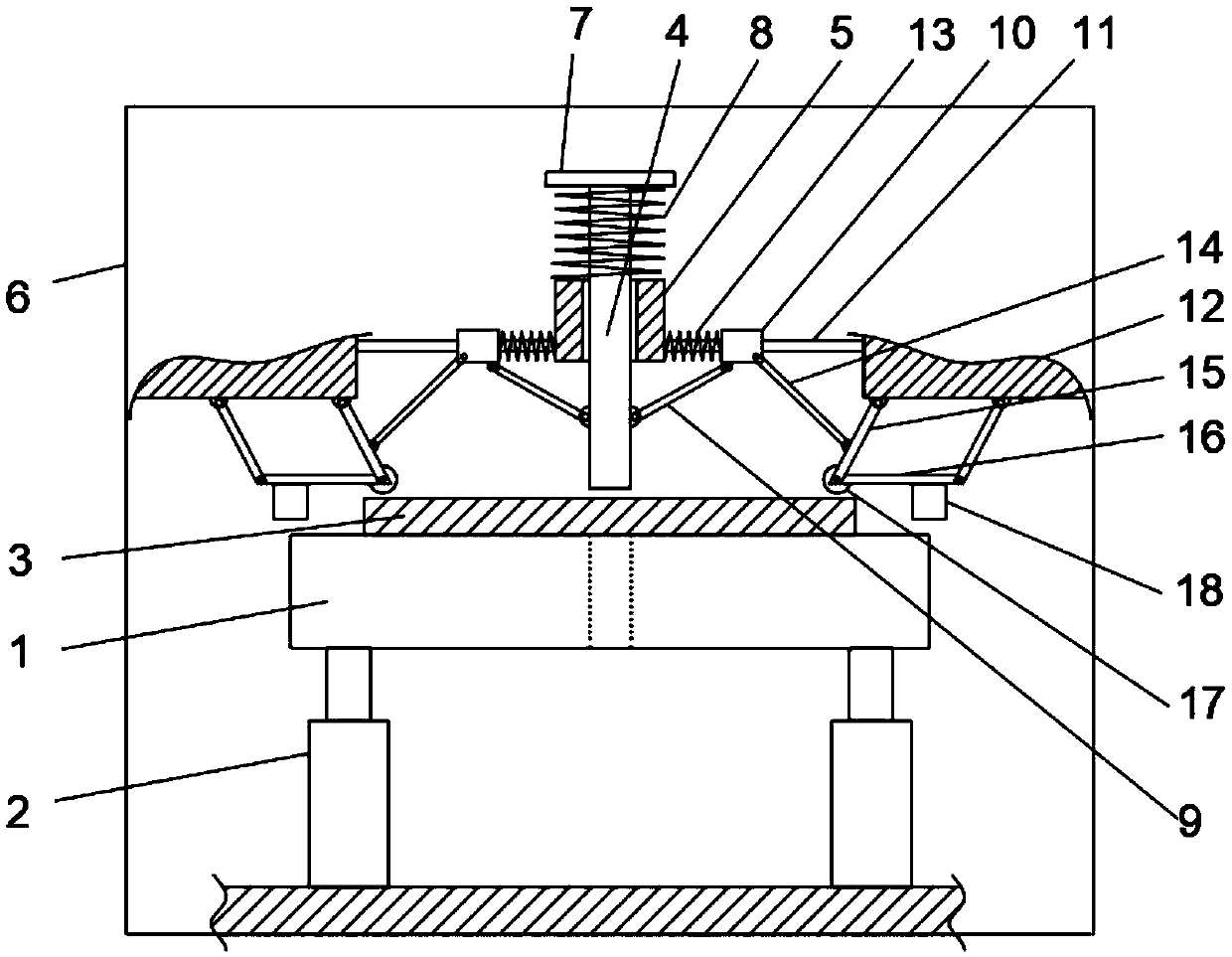
[0029] see Figure 1-2 , the present invention provides a technical solution:

[0030] A self-pressurized punching device, including a workbench 1, a cylinder 2 is provided under the workbench 1, the number of cylinders 2 can be set to two, and the workbench 1 is driven up and down by the cylinder 2, and the plate 3 is placed on the workbench 1 The upper surface of the upper surface of the plate 3 is vertically provided with a punching rod 4, and the workbench 1 is provided with a through hole with a diameter equal to or larger than the diameter of the punching rod 4, and the punching rod 4 slides through the hole. Over the limit block 5, the front side wall and the rear side wall of the limit block 5 are all fixed on the inner wall of the frame 6, and the top of the punching rod 4 is fixedly connected to the baffle plate 7 horizontally, between the baffle plate 7 and the limit block 5 The first spring 8 is arranged between the upper surface of the upper surface, the first sp...

Embodiment 2

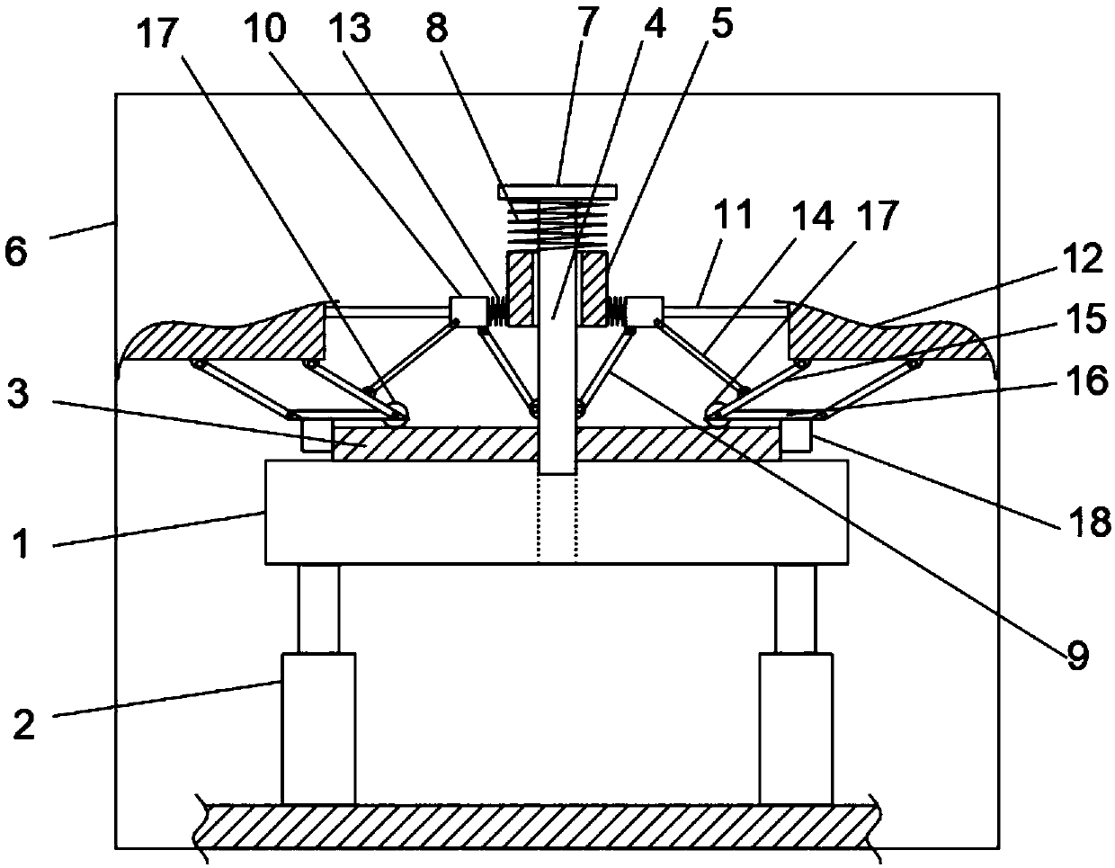
[0041] see image 3 , the second spring 13 arranged between the slider 10 and the limiting block 5 is replaced by a third spring 19 arranged between the slider 10 and the mounting block 12 , and the third spring 19 is sleeved on the slider 11 . The third spring 19 is a tension spring, which can also ensure the smooth movement of the slider 10 and the effective return of the slider 10 after the punching is completed. Other structures and principles are the same as those in Embodiment 1 and will not be repeated here.


PUM


Abstract

The invention discloses a self-pressing type hole punching device and a punching method. The self-pressing type hole punching device comprises a lifting workbench for bearing a punched part, a hole punching rod for punching the punched part, a locating device for clamping and locating the punched part, and a linkage device for linking the punched part and the locating device. The hole punching rod, the locating device and the linkage device are all located above the workbench, the locating device is located at the circumferential position of the hole punching rod, and the linkage device is connected with the hole punching rod and the locating device. According to the self-pressing type hole punching device and the punching method, the hole punching rod and the locating device can achieve linkage, and hole punching efficiency is improved.

Description

technical field [0001] The invention relates to the technical field of punching dies, in particular to a self-pressing punching device and a punching method. Background technique [0002] When the plate is punched, it needs to be positioned. In the process of processing, it is necessary to use a punching tool to punch a hole at a predetermined position on the surface. The existing plate positioning device cannot form a good linkage with the punching rod, resulting in the efficiency of punching. It is slow, the punching effect is not ideal, and there is room for improvement. Contents of the invention [0003] In view of the above problems, the present invention provides a self-pressing punching device and punching method, which can realize the linkage between the positioning device and the punching rod, and complete the punching after positioning the punched parts such as plates, which can Effectively solve the problems in the background technology. [0004] To achieve th...

Claims


Application Information

Patent Timeline
Patent Type & Authority Applications(China)
IPC IPC(8): B21D28/34B21D28/26B21D43/00
CPCB21D28/34B21D28/265B21D43/003
Inventor 陈嘉亮
Owner 陈嘉亮
Why Eureka
Try Eureka