
Mulching film recycling equipment

A technology for recycling equipment and mulch, applied in the fields of botanical equipment and methods, plant protection cover, gardening, etc., can solve the problems of laborious removal of roll mulch, easy adhesion, soil and environmental pollution, etc.

Active Publication Date: 2018-10-19
CHONGQING MEIQI IND
View PDF9 Cites 2 Cited by
  • Summary
  • Abstract
  • Description
  • Claims
  • Application Information

AI Technical Summary

Problems solved by technology

[0002] At present, the application of plastic film planting technology in agricultural production has been very common, bringing huge benefits to agriculture, but at the same time, due to the wide area of ​​plastic film laying and the difficulty of recycling, nearly 60% of the current domestic plastic film directly rots in the ground, which is harmful to soil and The environment has also brought great pollution and harm. The soil is hindered by white pollution and crop growth is severely lost.
[0003] Therefore, in the current production, people have paid full attention to the recycling of the used plastic film. At present, the recycling of the residual film is manual recycling, which is low in efficiency and labor-intensive; the second is mechanical recycling, which mainly uses roll film The roller rolls the mulch into a roll for recycling
[0004] In the process of mechanically recycling the plastic film, the soil is easy to adhere to the plastic film. After the plastic film is rolled into a roll, the soil will be mixed in the rolled plastic film. After the soil is dry, a lot of dust will be generated when the plastic film is used again, and due to Each roll of plastic film is larger in size and heavier in weight. At the same time, the inner ring of the roll of plastic film is closely attached to the rolling film roller, so it is more laborious to remove the roll of plastic film

Method used


Image

  • Mulching film recycling equipment
  • Mulching film recycling equipment
  • Mulching film recycling equipment

Examples


Embodiment Construction

[0024] Further detailed explanation through specific implementation mode below:

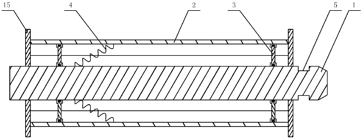
[0025] The reference signs in the accompanying drawings of the specification include: rolling film roller 1, stretching shell 2, stretching rod 3, return tension spring 4, locking groove 5, driving wheel 6, driven wheel 7, housing 8, swing lever 9 , Beating rod 10, bending rod 11, stretching rod 12, adjusting rod 13, correction frame 14, limit plate 15, arched frame 16, locking strip 17, locking disc 18, locking piece 19, clamping strip 20, cross bar 21, discharge tray 22, slide block 23, chute 24, discharge rod 25.

[0026] Such as figure 1 The mulch recovery equipment shown includes a traveling mechanism, a film rolling mechanism, a soil shaking mechanism and a power mechanism. The traveling mechanism includes four rollers, and the four rollers are joined together through a support frame, and a handrail is fixed on the support frame. A brake handle and a brake line that control the roller to ...


PUM


Abstract

The invention relates to the field of mulching film recycling and specifically relates to mulching film recycling equipment which comprises a support frame, a traveling mechanism, a film rolling mechanism, a soil shaking mechanism and a power mechanism for driving the soil shaking mechanism to shake soil; the film rolling mechanism comprises a film roller and a plurality of spreading units; the film roller is rotatably arranged on the support frame and is connected with the power mechanism; the spreading units are distributed around the film roller; each spreading unit comprises a spreading shell and two support rods; the two support rods are positioned at one end of the spreading shell respectively; one end of each spreading rod is articulated with the roller surface of the film roller, and the other end of each spreading rod is articulated with the spreading shell. In the technical scheme, the soil on the mulching film can be automatically shaken off in a film rolling process while the mulching film is easy to remove.

Description

technical field [0001] The invention relates to the field of plastic film recycling, in particular to a plastic film recycling device. Background technique [0002] At present, the application of plastic film planting technology in agricultural production has been very common, bringing huge benefits to agriculture, but at the same time, due to the wide area of ​​plastic film laying and the difficulty of recycling, nearly 60% of the current domestic plastic film directly rots in the ground, which is harmful to soil and The environment has also brought great pollution and harm. The soil is hindered by white pollution and crop growth is severely lost. [0003] Therefore, in the current production, people have paid full attention to the recycling of the used plastic film. At present, the recycling of the residual film is manual recycling, which is low in efficiency and labor-intensive; the second is mechanical recycling, which mainly uses roll film The roller rolls the mulch in...

Claims


Application Information

Patent Timeline
IPC IPC(8): A01G13/02
CPCA01G13/0287
Inventor 方智恒李姣姣
Owner CHONGQING MEIQI IND
Learn More