
Method for improving reliability of LLC resonant converter and related device

A resonant converter, reliable technology, applied in the field of power supply, can solve the problems of MOSFET failure and low reliability

Active Publication Date: 2018-10-16
VERTIV CORP
View PDF5 Cites 10 Cited by
  • Summary
  • Abstract
  • Description
  • Claims
  • Application Information

AI Technical Summary

Problems solved by technology

[0006] The embodiment of the present invention provides a method and a related device for improving the reliability of an LLC resonant converter, which are used to solve the problems caused by the power-on, load jump and input jump of the LLC resonant converter using a silicon-based MOSFET body diode as the primary switching device. The problem of low reliability caused by MOSFET failure caused by time-varying operation in the ZCS region

Method used


Image

  • Method for improving reliability of LLC resonant converter and related device
  • Method for improving reliability of LLC resonant converter and related device
  • Method for improving reliability of LLC resonant converter and related device

Examples


Embodiment 1

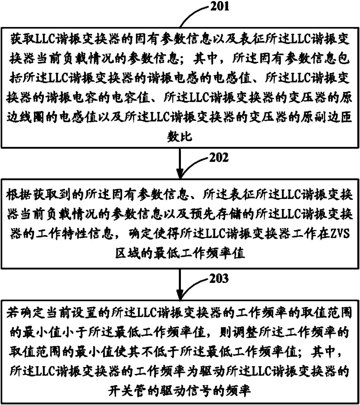
[0042] Embodiment 1 of the present invention provides a method for improving the reliability of an LLC resonant converter, specifically, as figure 2 As shown, it is a flow chart of the steps of the method described in Embodiment 1 of the present invention, and the method may include the following steps:

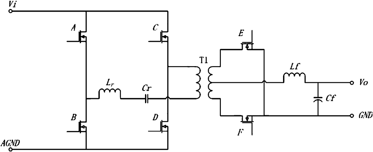
[0043] Step 201: Obtain the inherent parameter information of the LLC resonant converter and the parameter information characterizing the current load condition of the LLC resonant converter; wherein, the inherent parameter information includes the inductance value of the resonant inductance of the LLC resonant converter, the The capacitance value of the resonant capacitor of the LLC resonant converter, the inductance value of the primary coil of the transformer of the LLC resonant converter, and the primary-to-secondary turns ratio of the transformer of the LLC resonant converter.

[0044] Optionally, the LLC resonant converter may include any one of a full-bridge LLC reson...

Embodiment 2

[0069] Based on the same inventive concept, Embodiment 2 of the present invention provides a device for improving the reliability of an LLC resonant converter, specifically, as Figure 6 As shown, it is a schematic structural diagram of the device described in Embodiment 2 of the present invention, and the device may include:

[0070] An acquisition unit 601, configured to acquire intrinsic parameter information of the LLC resonant converter and parameter information characterizing the current load condition of the LLC resonant converter; wherein, the intrinsic parameter information includes the inductance value of the resonant inductance of the LLC resonant converter , the capacitance value of the resonant capacitor of the LLC resonant converter, the inductance value of the primary coil of the transformer of the LLC resonant converter, and the primary-to-secondary turns ratio of the transformer of the LLC resonant converter;

[0071] The calculation unit 602 is configured to ...


PUM


Abstract

A method for improving reliability of LLC resonant converter and related device can obtain the intrinsic parameter information of the LLC resonant converter and the parameter information of the current load condition of the LLC resonant converter. According to the intrinsic parameter information, the parameter information of the current load condition of the LLC resonant converter and the workingcharacteristic information of the LLC resonant converter which is pre-stored in advance, the LLC resonant converter is determined to operate at the lowest operating frequency value of the ZVS region.If the minimum value of the value range of the operating frequency of the currently set LLC resonant converter is determined to be smaller than the lowest operating frequency value, the minimum valueof the value range of the operating frequency is adjusted to be not lower than the lowest operating frequency value. That is to say, according to the load condition, the minimum value of the operatingfrequency of the LLC resonant converter can be adjusted in real time. It is ensured that the LLC resonant converter always operates in ZVS mode. The reliability of the LLC resonant converter is effectively improved.

Description

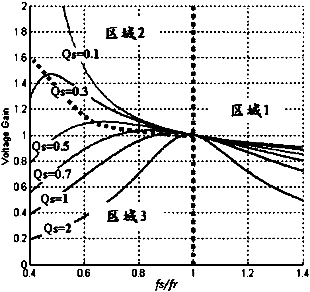
technical field [0001] The invention relates to the technical field of power supplies, in particular to a method and a related device for improving the reliability of an LLC resonant converter. Background technique [0002] At present, switching power supplies are developing toward high power density and high efficiency. LLC resonant converters are being used more and more widely because of their excellent soft switching characteristics and boosting capabilities. [0003] Such as figure 1 Shown is a schematic diagram of the operating characteristics of the LLC resonant converter, where the ordinate is the absolute value of the voltage conversion rate, the abscissa is the ratio of the operating frequency fs of the LLC resonant converter to the resonant frequency fr of the LLC resonant converter, and Qs is the quality factor. According to the DC gain characteristics of the LLC resonant converter, its working mode can be divided into three working areas, area 1 and area 2 are...

Claims


Application Information

Patent Timeline
IPC IPC(8): H02M3/335
CPCH02M3/33569H02M1/0058Y02B70/10
Inventor 刘韧首福俊李清纯
Owner VERTIV CORP
Learn More