
Heat exchange device

A heat exchange device and technology for exchanging heat, applied to electrochemical generators, electrical components, circuits, etc., can solve problems such as poor heat exchange capacity and long heat exchange time

Pending Publication Date: 2018-10-16
WM SMART MOBILITY (SHANGHAI) CO LTD
View PDF11 Cites 6 Cited by
  • Summary
  • Abstract
  • Description
  • Claims
  • Application Information

AI Technical Summary

Problems solved by technology

[0004] In order to overcome the above defects, the present invention aims to provide a heat exchange device to solve the problems of poor heat exchange capacity and long heat exchange time in the heat exchange device of the power battery

Method used


Image

  • Heat exchange device
  • Heat exchange device
  • Heat exchange device

Examples


Embodiment Construction

[0036] The present invention will be described in detail below in conjunction with the accompanying drawings and specific embodiments. Note that the aspects described below in conjunction with the drawings and specific embodiments are only exemplary, and should not be construed as limiting the protection scope of the present invention.

[0037] In order to solve the problems of low heat exchange efficiency and long heat exchange time in existing power battery heat exchange devices, a heat exchange device is provided in this case.

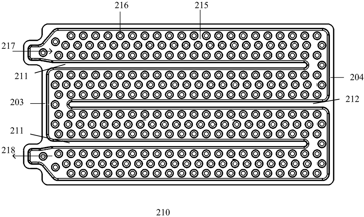
[0038] In one embodiment, as figure 2 As shown, the heat exchange device includes a first plate (not shown) and a second plate 210 .

[0039] The first plate is a metal plate, which is used to contact the power battery after being covered with heat-conducting silica gel.

[0040] The second flat plate 210 is a metal flat plate, and a concave portion is formed after stamping. When the periphery of the second flat plate 210 is welded or punched but...


PUM

PropertyMeasurementUnit
depthaaaaaaaaaa
depthaaaaaaaaaa
radiusaaaaaaaaaa

Abstract

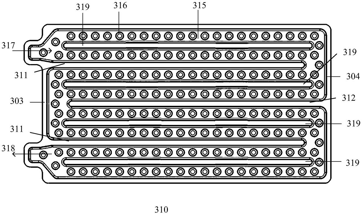
The invention provides a heat exchange device. The heat exchange device is used for exchanging heat with a battery and comprises a first flat plate and a second flat plate, wherein the second flat plate is connected to the first flat plate in a butt joint mode; the second flat plate comprises a concave part so as to form a cavity with the first flat plate and further comprises a plurality of firstfinger-shaped partitions extending from a first side end to a second side end and a plurality of second finger-shaped partitions extending from the second side end to the first side end; the multiplefirst finger-shaped partitions and the second finger-shaped partitions are arranged in a staggered mode so as to enable the cavity to form a circuitous flow channel; and turbulent flow pits which aresunken towards the outside of the flow channel are arranged on the flow channel.

Description

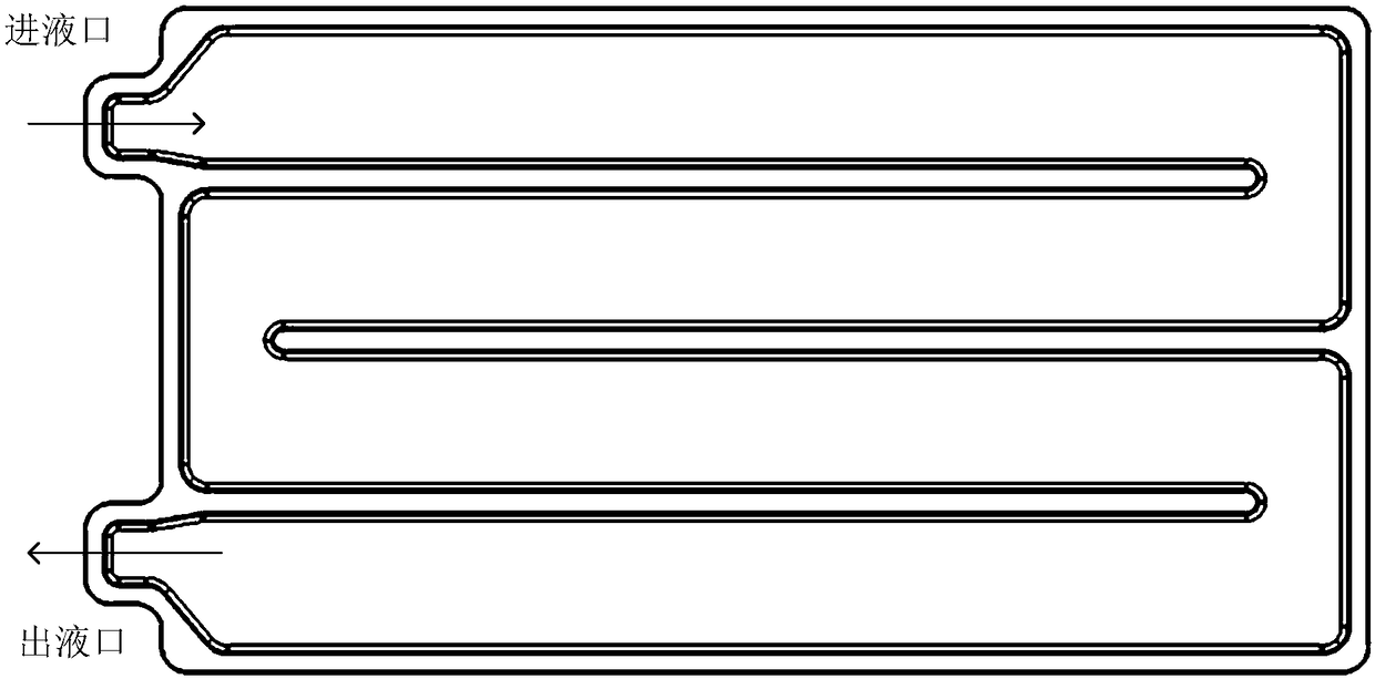
technical field [0001] The invention relates to a heat exchange device, in particular to a liquid cooling plate used for heat exchange with a power battery. Background technique [0002] A general power battery cooling device consists of an external cooling device such as Chiller, an external heating device such as a PTC positive temperature coefficient heater, a heat exchange device such as a water-cooled plate, heat-conducting silica gel, pipelines, valves, etc., and the battery is placed on one side of the water-cooled plate On the plate, there is a thermally conductive silicone pad between the battery cell and the water cooling plate. [0003] figure 1 It is a schematic diagram of the heat exchange device of the existing common water-cooling scheme. In the existing battery pack that uses the water-cooled plate as the cooling scheme, the cooling liquid enters the heat exchange device from the liquid inlet. The power battery performs heat exchange, and finally flows out ...

Claims


Application Information

Patent Timeline
Patent Type & Authority Applications(China)
IPC IPC(8): H01M10/613H01M10/625H01M10/6554H01M10/6556H01M10/6568
CPCH01M10/613H01M10/625H01M10/6554H01M10/6556H01M10/6568Y02E60/10
Inventor 王涛朱菲向建明张明刘钢
Owner WM SMART MOBILITY (SHANGHAI) CO LTD
Learn More