
Electromagnetic test probe, electromagnetic test device and electromagnetic test method

An electromagnetic and testing signal line technology, applied in measuring devices, measuring leads/probes, components of electrical measuring instruments, etc., can solve problems such as affecting product performance, generating noise, and common mode interference of motherboards, achieving convenient operation, Noise removal, simple structure effect

Active Publication Date: 2018-10-16
GEER TECH CO LTD
View PDF14 Cites 5 Cited by
  • Summary
  • Abstract
  • Description
  • Claims
  • Application Information

AI Technical Summary

Problems solved by technology

[0003] Coils are commonly used in the speakers of existing electronic products, and it is easy to cause common-mode interference due to the electromagnetic radiation of the motherboard during work, resulting in noise and affecting product performance.
Specifically: if there is high-frequency radiation on the working motherboard, such as radio frequency signals or motherboard clocks, the envelope of these signals in the audible frequency band is likely to fluctuate; it can be known from Lenz's law that when the coil is in an electromagnetic field of a certain frequency , the inside of the coil will generate a potential difference opposite to the changing trend due to electromagnetic induction, and an electrical signal with the same frequency as the electromagnetic radiation signal will be induced; the electrical signal will cause common-mode interference through the audio equipment, resulting in noise

Method used


Image

  • Electromagnetic test probe, electromagnetic test device and electromagnetic test method
  • Electromagnetic test probe, electromagnetic test device and electromagnetic test method
  • Electromagnetic test probe, electromagnetic test device and electromagnetic test method

Examples


Embodiment Construction

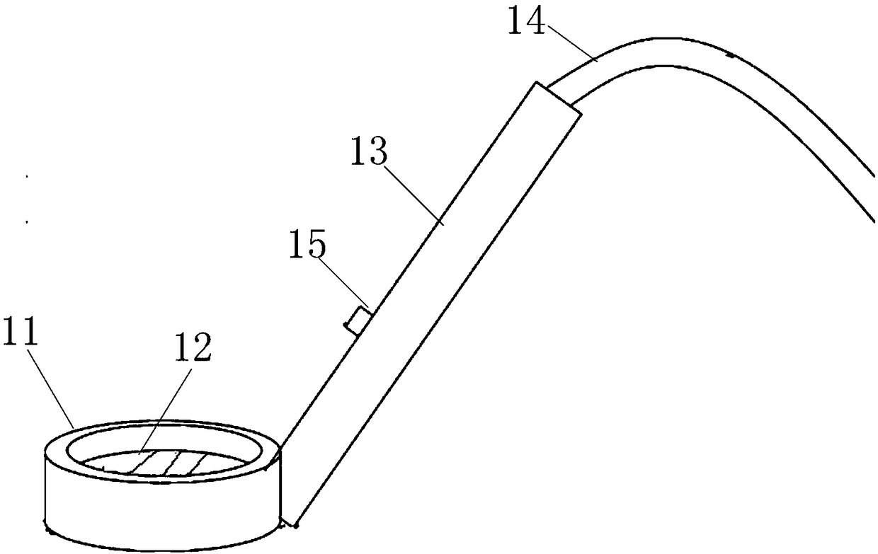
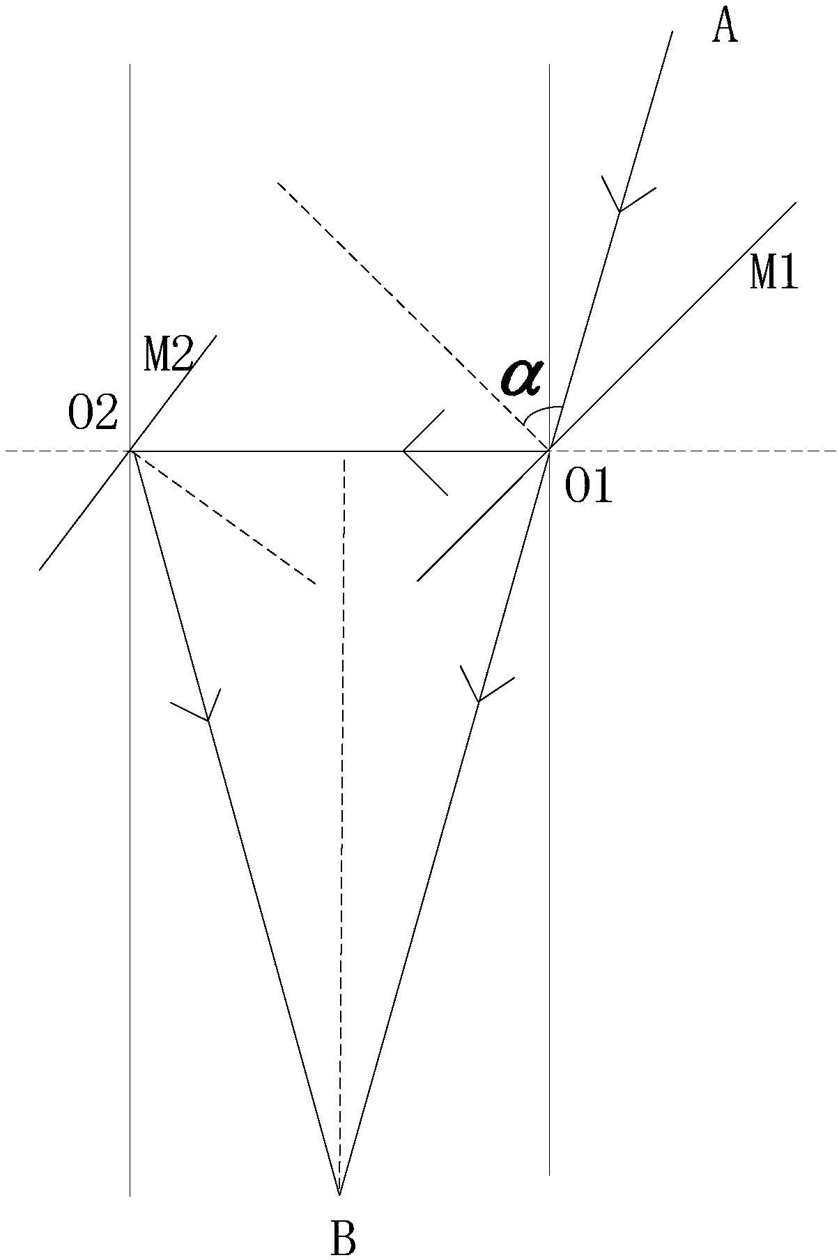
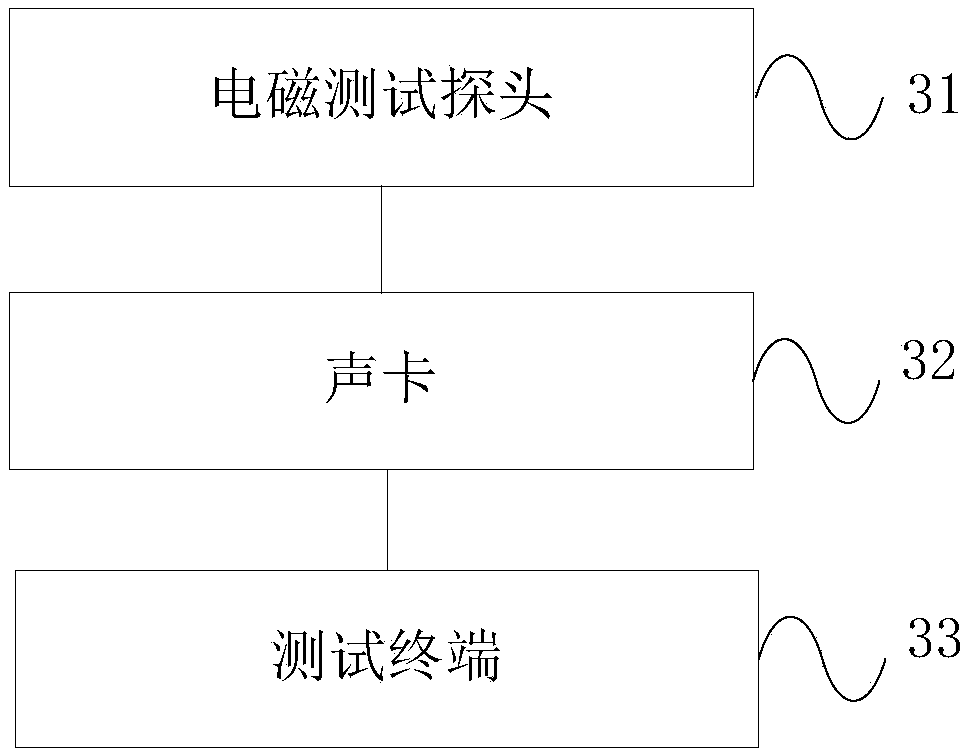
[0041] In order to solve the technical problems raised in the background technology, the inventors of the present application thought of designing an electromagnetic test probe with simple structure and convenient operation, which only includes a hollow positive cylinder and a handle, and the side walls around the positive cylinder are equipped with There are induction coils, semi-transmissive mirrors and reflectors. There is flat glass on the bottom of the positive cylinder. Laser generators and test signal lines are installed inside the handle. The tester holds the handle of the electromagnetic test probe close to the main board to be tested, and then the electromagnetic Radiation measurement, easy to operate. The present invention also designs an electromagnetic testing device comprising the above-mentioned electromagnetic testing probe and an electromagnetic testing method using the electromagnetic testing device. Through the electromagnetic testing device, the electromagne...


PUM


Abstract

The invention discloses an electromagnetic test probe, an electromagnetic test device and an electromagnetic test method. The electromagnetic test probe comprises: a hollow positive cylinder, whereinan induction coil is wound around the peripheral wall of the positive cylinder, a flat glass is arranged on the bottom surface of the positive cylinder, and a circular dial is drawn on the surface ofthe flat glass; and a holding rod, wherein the bottom of the holding rod is connected to the side surface of the positive cylinder, a laser generator and a test signal line are arranged inside the holding rod, the positive pole of the test signal line is connected with the first end of the induction coil, and the negative pole of the test signal line is connected with the second end of the coil. The bottom of the holding rod is provided with an opening, an inclined semi-transmissive mirror is arranged in one side wall of the positive cylinder at a position corresponding to the opening, and aninclined reflector is arranged in the other side wall of the positive cylinder and opposite to the semi-transmissive mirror. The invention can intuitively and conveniently measure the radiation statenear a mainboard to be tested, and provides a reliable reference for the layout and structural design of the mainboard component, thereby eliminating the noise generated by the common mode interference of the acoustic related product from the design.

Description

technical field [0001] The invention relates to the technical field of electronic product testing, in particular to an electromagnetic testing probe, an electromagnetic testing device and an electromagnetic testing method. Background technique [0002] With the development of the electronics industry, convenience and lightweight have become hard targets for product design, and structural nesting and size reduction have become important steps in the design process. [0003] Coils are commonly used in the speakers of existing electronic products, which are prone to common-mode interference caused by the electromagnetic radiation of the motherboard during operation, resulting in noise and affecting product performance. Specifically: if there is high-frequency radiation on the working motherboard, such as radio frequency signals or motherboard clocks, the envelope of these signals in the audible frequency band is likely to fluctuate; it can be known from Lenz's law that when the...

Claims


Application Information

Patent Timeline
Patent Type & Authority Applications(China)
IPC IPC(8): G01R31/00G01R1/06G01R1/02
CPCG01R1/02G01R1/06G01R31/001
Inventor 黄勃文
Owner GEER TECH CO LTD
Learn More