Lifting mechanism and lifting device applying lifting mechanism

A technology for installing blocks and driving motors, which is applied in the direction of lifting devices, etc., can solve the problems of large weight and volume of forklifts, reduced logistics efficiency, and high robot height, and achieves the effect of overall structure optimization.

Active Publication Date: 2018-10-16
SUZHOU XINYOUHUA INVESTMENT ADVISOR CO LTD
View PDF4 Cites 7 Cited by
  • Summary
  • Abstract
  • Description
  • Claims
  • Application Information

AI Technical Summary

Problems solved by technology

[0003] For the above-mentioned manual hydraulic pallet trucks and manned electric or fuel forklifts, they are manually operated equipment and do not meet the requirements of factory automation
For a fully autonomous navigation forklift, it is transformed from a manned forklift. When the double fork lifts the pallet, since the weight of the pallet is concentrated on one side of the forklift (on the double fork), it is necessary to counterweight the body, so that the forklift The self-weight and volume of the car are relatively large; or the supporting wheels are installed under the double forks, but due to the need to install modules such as the lifting mechanism and the driving mechanism, the volume and weight of the front part are relatively large
And due to the limitation of volume structure and size, the driving mechanism can only be installed on the front side of the forklift, so it cannot be transformed in situ, and has a large turning radius
[0004] For a submerged autonomous navigation robot with a certain height, the drive form of two-wheel differential or steering wheel is generally used, but this type of robot is high in height and cannot be inserted under the pallet like a forklift, and the pallet needs to be placed on a customized height. on the pallet rack, so that the robot can sneak under the pallet rack, and then use the robot's own lifting function to lift the pallet rack together with the pallet above and transport it to the designated position
In the above-mentioned handling method, each pallet needs to be equipped with a fixed-value pallet rack, and the goods need to be placed on the pallet rack every time before lifting, which reduces logistics efficiency and increases transportation costs.

Method used


Image

  • Lifting mechanism and lifting device applying lifting mechanism
  • Lifting mechanism and lifting device applying lifting mechanism
  • Lifting mechanism and lifting device applying lifting mechanism

Examples


Embodiment Construction

[0028] The present invention will be further described below in conjunction with the accompanying drawings and specific embodiments, so that those skilled in the art can better understand the present invention and implement it, but the examples given are not intended to limit the present invention.

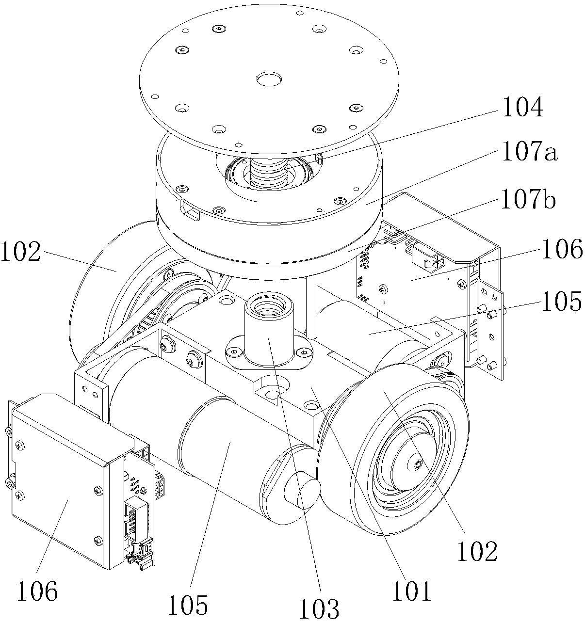
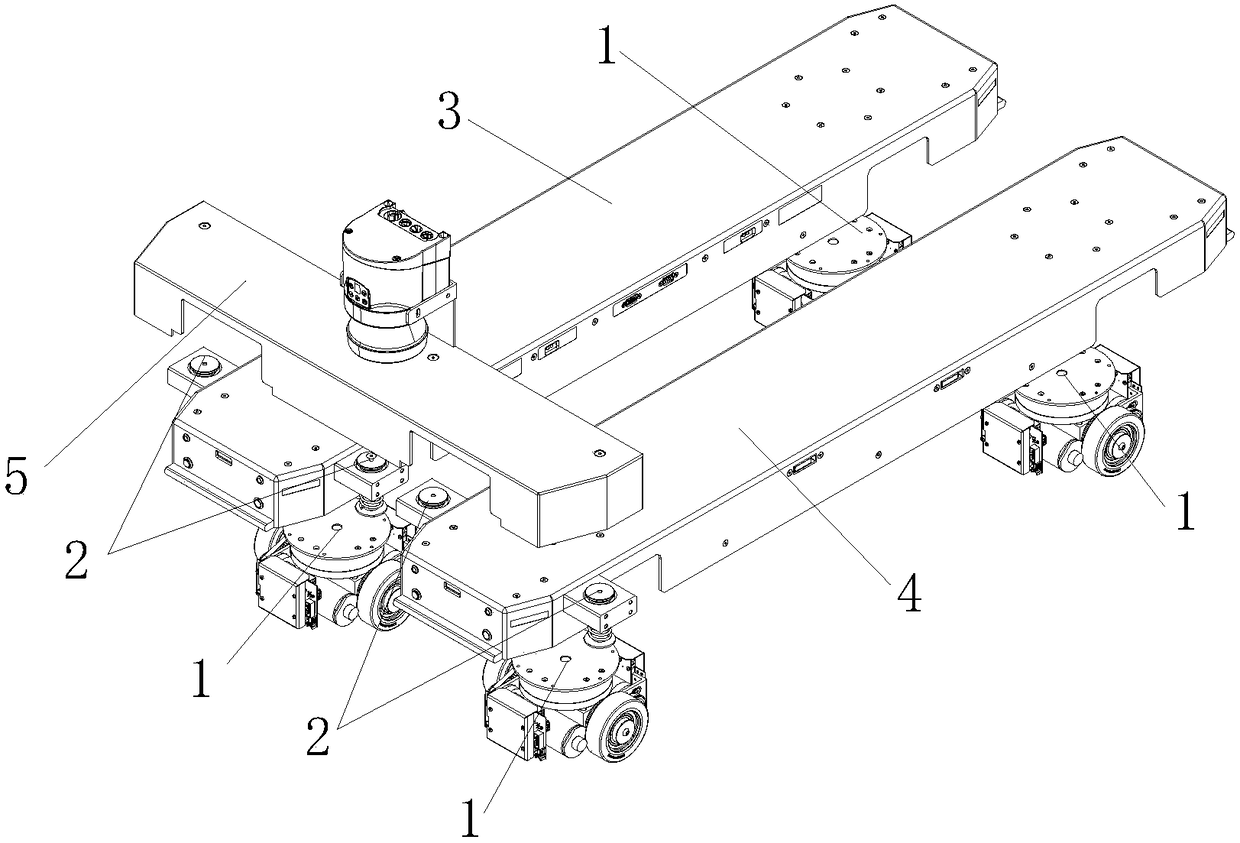
[0029] combine figure 1 As shown, the present invention discloses a lifting mechanism installed on a lifting device. In the present invention, the preferred lifting device is a transport robot. The transportation robot includes a carrying unit, and a lifting mechanism 1 arranged at the bottom of the carrying unit and abutting against the carrying unit. The lifting mechanism 1 includes a driving component and a lifting component, and the lifting mechanism can realize a lifting function and a driving function through the same set of driving components. The driving assembly includes a wheel shaft fixing block 101 , driving wheels 102 arranged on the left and right sides of the wheel...


PUM


Abstract

The invention discloses a lifting mechanism. The lifting mechanism is installed on a lifting device. The lifting device comprises a bearing unit, the lifting mechanism is arranged at the bottom of thebearing unit, the lifting mechanism comprises a driving assembly and a lifting assembly, the driving assembly comprises a wheel shaft fixing block, driving wheels and a power source, the lifting assembly comprises a screw rod nut, and a screw rod, and the upper end of the screw rod is fixedly connected with the bearing unit. When the lifting mechanism advances, all the driving wheels make contactwith the foundation surface and move the lifting device on the foundation surface; and when the lifting mechanism is used for lifting, all the driving wheels rotate on the foundation surface to drivethe screw rod nut to rotate relative to the bearing unit in the vertical direction so as to drive the screw rod to move in the vertical direction to lift the bearing unit. The multi-angle rotating device at least has the following advantages that multi-angle rotation of all the driving wheels can be realized., the moving of the conveying robot and the lifting of the lifting mechanism are realizedunder the action of the same driving assembly;

Description

technical field [0001] The invention relates to the technical field of lifting mechanisms, in particular to a lifting mechanism and a lifting device using the lifting mechanism. Background technique [0002] As the logistics carrier in the factory, the pallet occupies an important part in the factory logistics. At present, the equipment used to lift and transport pallets mainly includes manually operated manual hydraulic pallet trucks and electric or fuel forklifts. With the development of robot technology, there has been a fully autonomous navigation forklift for handling pallets, which can insert pallets placed on the ground to achieve the purpose of transportation; another pallet handling robot is to place pallets on a customized On the pallet rack with the highest height, the handling robot sneaks under the pallet rack to lift the pallet rack together with the pallet and transport it to the designated location. [0003] For the above-mentioned manual hydraulic pallet t...

Claims


Application Information

Patent Timeline
Patent Type & Authority Applications(China)
IPC IPC(8): B66F9/20B66F9/24B66F9/075
CPCB66F9/0755B66F9/07568B66F9/07572B66F9/07586B66F9/20B66F9/24B66F9/063
Inventor 戴军王宏军
Owner SUZHOU XINYOUHUA INVESTMENT ADVISOR CO LTD
Why Eureka
Try Eureka