FPGA-based dynamic partial reconfiguration system and method

A technology for dynamic partial reconfiguration and storage of subsystems, applied to the architecture with a single central processing unit, CAD circuit design, digital computer components, etc., can solve the problem of reducing the secondary development characteristics of reconfiguration technology, low real-time Reduce structural efficiency and other issues, achieve the effect of shortening the time of data interaction, shortening the development cycle, and improving the configuration speed

Active Publication Date: 2021-09-17
BEIHANG UNIV
View PDF6 Cites 0 Cited by
  • Summary
  • Abstract
  • Description
  • Claims
  • Application Information

AI Technical Summary

Problems solved by technology

[0003] (1) Poor flexibility and low real-time performance
[0004] Dynamic reconfiguration technology relies heavily on the development kits and tools provided by FPGA manufacturers, but these do not support users to carry out secondary development according to functional requirements, and do not provide corresponding software and hardware programming interfaces. Users can only develop according to the specified The process conducts simple refactoring experiments, which weakens the flexibility of refactoring the system
In addition, since the development kit provided by the FPGA supplier cannot schedule the refactoring process in real time, the refactoring efficiency is low, and the refactoring technology lacks real-time performance
[0005] (2) Lack of communication mechanism between reconstructed hardware and upper-layer software
In the application process of dynamic reconfiguration technology, the reconfiguration design distributed in the underlying hardware lacks a communication mechanism with the upper layer software, so that the reconfiguration application is often carried out without software, which greatly reduces the characteristics of the secondary development of reconfiguration technology , and the possibility of combining application of reconfiguration technology and embedded system

Method used


Image

  • FPGA-based dynamic partial reconfiguration system and method
  • FPGA-based dynamic partial reconfiguration system and method
  • FPGA-based dynamic partial reconfiguration system and method

Examples


Embodiment Construction

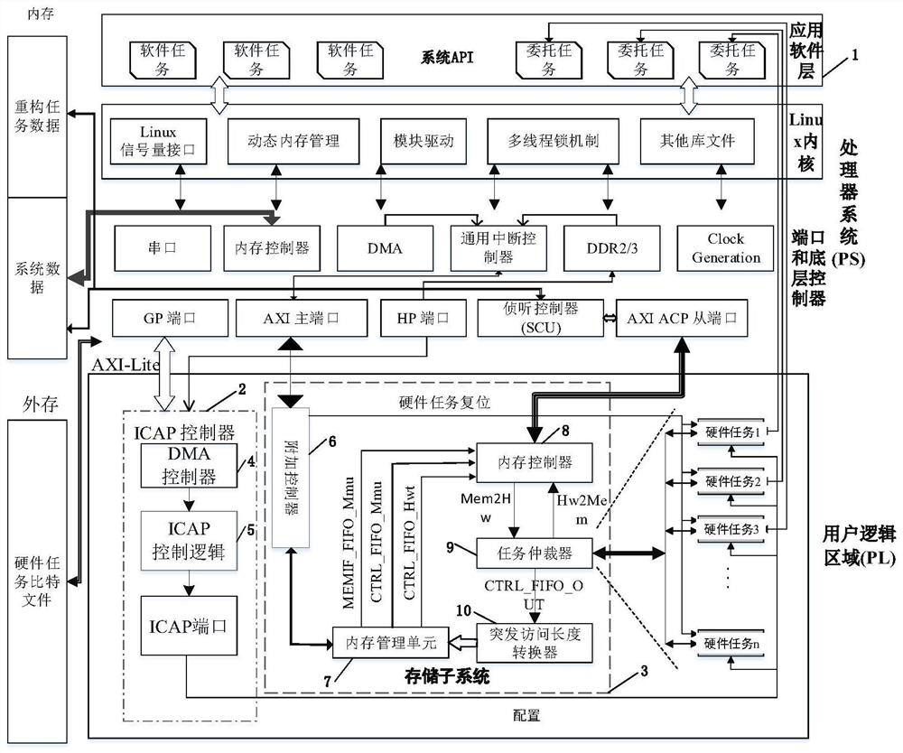
[0031] The present invention provides an FPGA-based dynamic partial reconfiguration system, the purpose of which is to provide users with a programming model composed of hardware tasks, software tasks and entrusted tasks, and realize dynamic loading of hardware tasks through dynamic reconfiguration technology, design And realized the storage subsystem used for data interaction between hardware task and system application software layer. The system reduces the difficulty of reconfiguration application development, reduces the user's direct operation on the underlying hardware of the device, and accelerates the development speed of reconfiguration applications.

[0032] The invention provides a dynamic partial reconfiguration system based on FPGA, and its technical scheme is: on the basis of the multi-thread programming model of the embedded Linux system, combined with the partial dynamic reconfiguration characteristics of FPGA, a system based on hardware tasks and software tasks...


PUM


Abstract

The present invention provides an FPGA-based dynamic partial reconfiguration system and method, including a reconfiguration task development model, an ICAP controller and a storage subsystem; the reconfiguration task development model includes software tasks, hardware tasks and entrusted tasks; the software tasks are based on In the development of Linux multi-threading, the hardware task is a logic circuit implemented by VHDL with interface specifications, and the entrusted task is a lightweight Linux thread. Through the entrusted task, the hardware task can be controlled like controlling the software task; the ICAP controller is controlled by the DMA controller. and ICAP control logic; the storage subsystem is composed of additional controllers, memory management units, memory controllers, task arbitrators, and burst access length converters. The invention realizes the data interaction between the hardware task and the system application software layer, reduces the difficulty of developing the reconfiguration application, reduces the direct operation of the user on the underlying hardware of the device, and accelerates the development speed of the reconfiguration application.

Description

(1) Technical field: [0001] The present invention is based on the dynamic partial reconfiguration system of FPGA {FPGA is the abbreviation of Field Programmable Gate Array (Field Programmable Gate Array)}, it is a kind of embedded operating system based on the dynamic reconfiguration technology of FPGA, especially a kind of based on A dynamic reconfiguration technology development platform for an embedded Linux system realizes rapid secondary development and application of the dynamic reconfiguration technology, and belongs to the field of computer technology. (two) background technology: [0002] The advantages of dynamic reconfiguration technology in digital circuit design are valuable in many research fields, but because it is closely related to the underlying logic resources of FPGA devices, and the current FPGA integration scale has reached more than one million gates and the types of on-chip resources are also limited. More and more, therefore, this technology faces th...

Claims


Application Information

Patent Timeline
Patent Type & Authority Patents(China)
IPC IPC(8): G06F30/347G06F15/78G06F115/02
CPCG06F15/7871G06F30/331G06F30/392G06F2117/08
Inventor 王国华申展余罗东明
Owner BEIHANG UNIV
Why Eureka
Try Eureka