
LMR microstructure optical fiber

A microstructure fiber and fiber core technology, applied in cladding fibers, light guides, optics, etc., can solve difficulties and other problems, and achieve the effects of easy acquisition, real-time monitoring, and favorable filling.

Pending Publication Date: 2018-10-12
NORTHEASTERN UNIV
View PDF10 Cites 14 Cited by
  • Summary
  • Abstract
  • Description
  • Claims
  • Application Information

AI Technical Summary

Problems solved by technology

[0005] However, the existing microstructure sensing structure is relatively difficult to coat or fill the analyte because the air holes are too small (generally a few microns).
Moreover, the current microstructure optical fiber sensing based on traditional principle detection is relatively mature, and it is difficult to make a breakthrough in measurement sensitivity and accuracy. very important

Method used


Image

  • LMR microstructure optical fiber
  • LMR microstructure optical fiber
  • LMR microstructure optical fiber

Examples


Embodiment 1

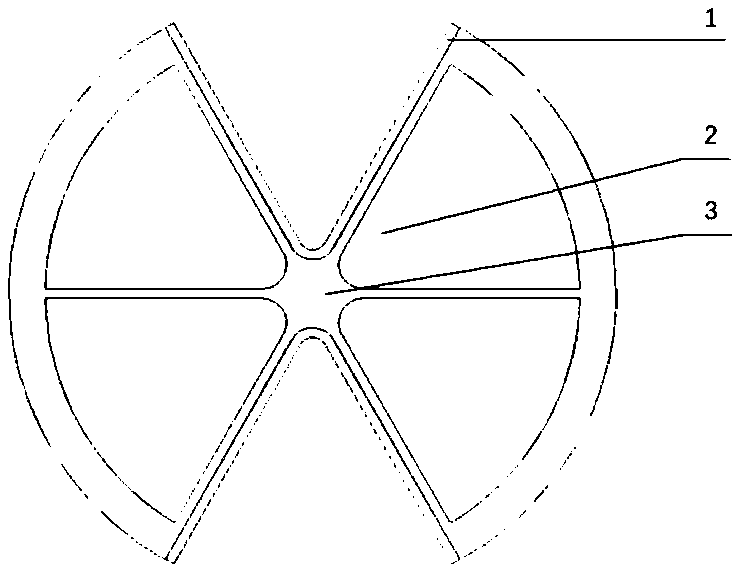
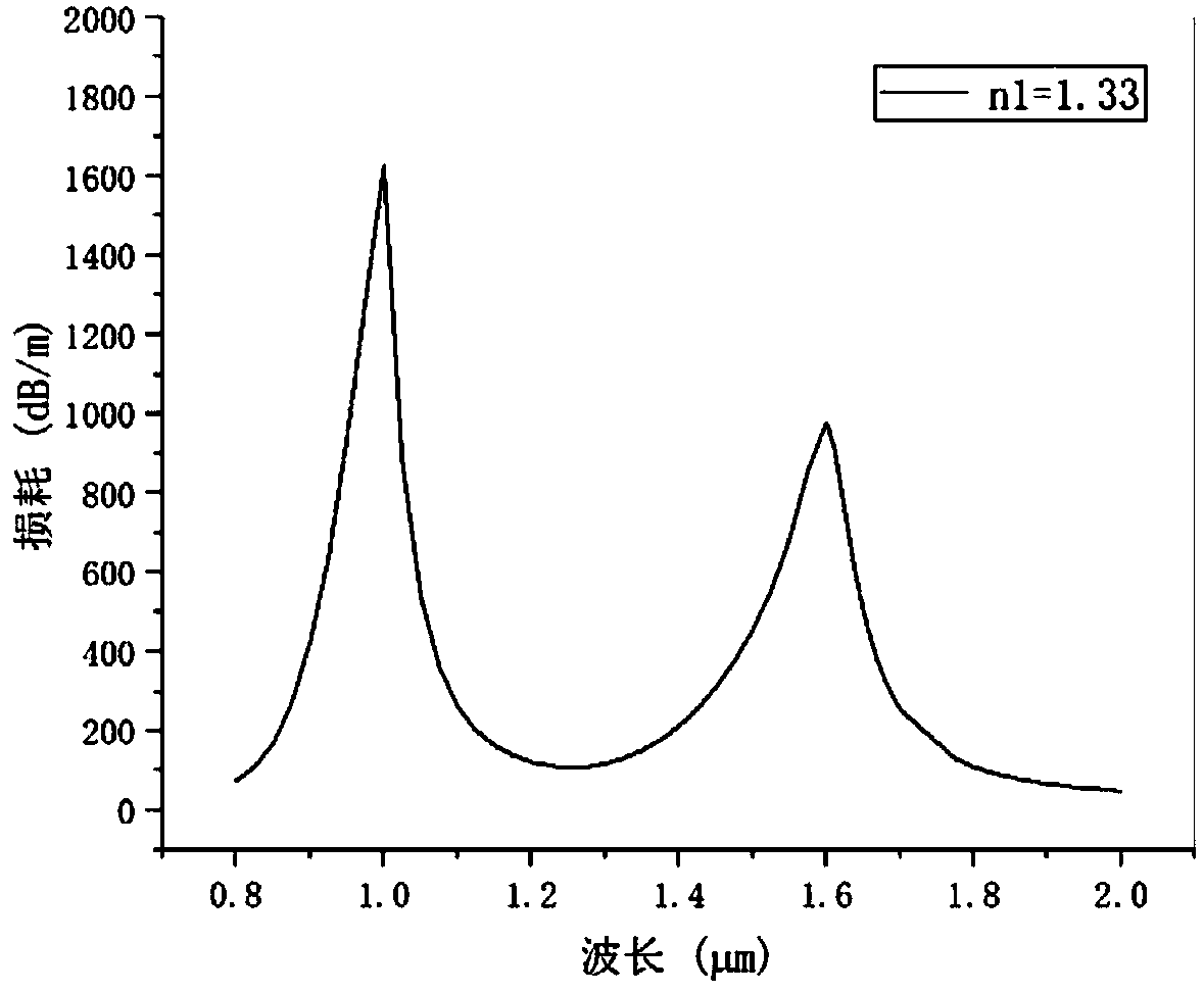
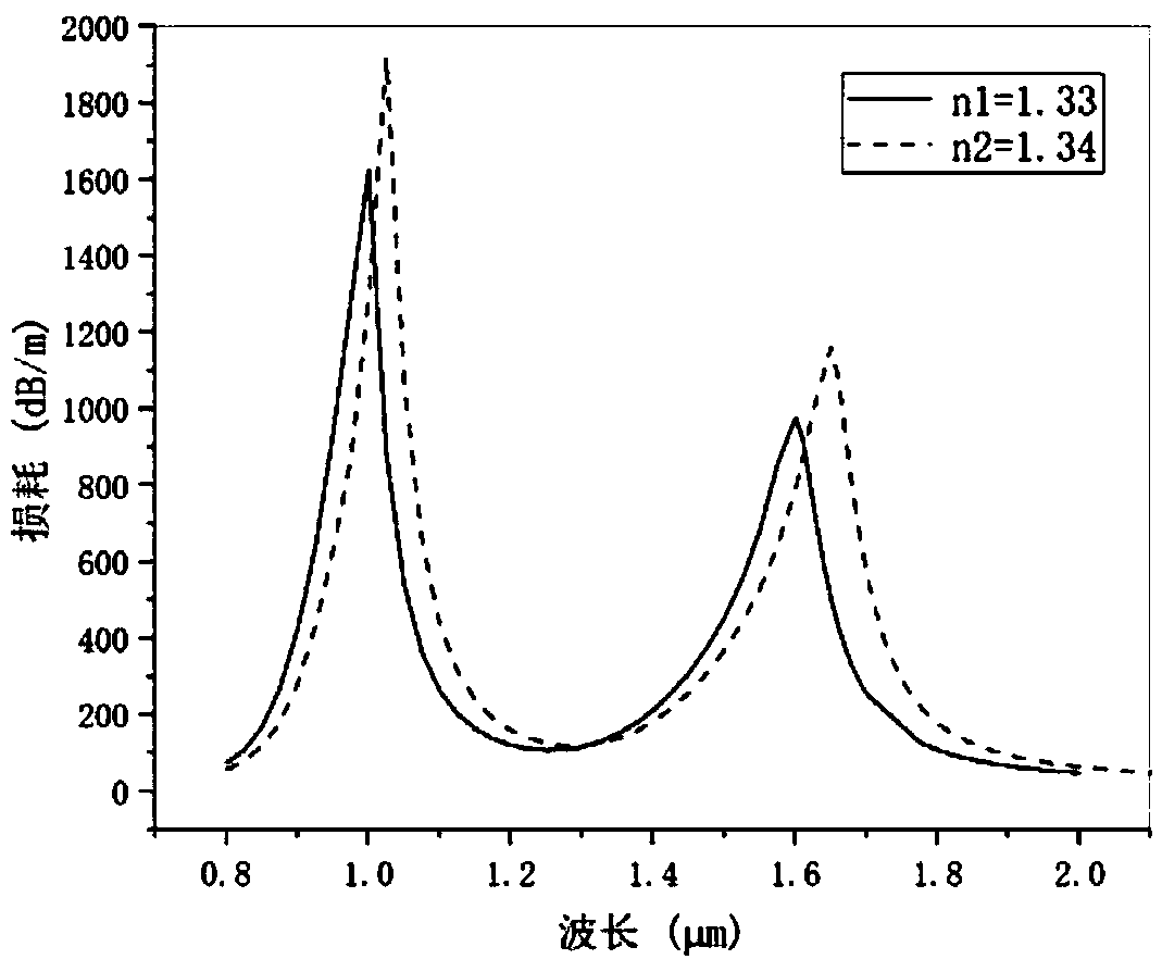
[0035] Such as figure 1As shown, the present invention provides a kind of LMR microstructure optical fiber, which adopts the core cladding structure, the outer diameter of the core is 125um, the material is quartz glass, there is no air hole in the center of the core, and the core diameter is 15um. There are six fan-shaped air holes of the same size arranged in a regular hexagon in the cladding, the diameter of the fan-shaped air holes is 100um, the distance between adjacent fan-shaped air holes is 2um, and its refractive index is 1, which will be relative to The roughly symmetrical fan-shaped air hole in the center of the fiber core 3 is opened to communicate with the outside world. Therefore, the fiber optic probe can be directly put into the fluid to be measured for filling, and the light transmitted in the fiber core is easier to pass through the film and the fluid. Loss mode resonance is carried out, so that the resonance trough is more obvious, and the accuracy of the se...


PUM


Abstract

The invention provides an LMR microstructure optical fiber. The LMR microstructure optical fiber comprises a fiber core,cladding and four air holes located in the cladding,and adopts a fiber core cladding structure,no air hole is formed in the center of the fiber core,six fan-shaped air holes are same in size and are arranged in the shape of a regular hexagon,the hole medium refractive index is 1,and each fan-shaped air hole comprises a first cambered surface and a second cambered surface,wherein the second cambered surface is longer than the first cambered surface,and the second cambered surface is arranged to be away from the fiber core,two air holes roughly symmetrical relative to the center of the fiber core in the fan-shaped air hole are split so as to be communicated with the outsideworld,and TiO2 thin films are plated on the surfaces of the two split air holes. By means of the LMR microstructure optical fiber,not only the thin film materials are cheap,but also the flexibility and precision are greatly improved compared with a traditional sensor,and meanwhile film plating and to-be-tested fluid filling are facilitated.

Description

technical field [0001] The present invention relates to the technical field of microstructured optical fiber, in particular to LMR microstructured optical fiber. Background technique [0002] In the 1980s, as an excellent low-loss transmission line, optical fiber began to enter people's sight, and sensors based on optical fiber as a waveguide also became in full swing. Optical fiber sensors have incomparable advantages compared to traditional sensors: anti-magnetic interference, electrical insulation, good explosion-proof performance, corrosion resistance, good light guide performance, multi-parameter measurement, small size, and embeddability, etc. It is easy to form a sensor network, and Access to the Internet and Wi-Fi. [0003] However, the optical fiber sensor using ordinary optical fiber as the sensitive element has several insurmountable shortcomings such as large coupling loss, poor polarization-maintaining characteristics, and cross-sensitivity problems, which limi...

Claims


Application Information

Patent Timeline
Patent Type & Authority Applications(China)
IPC IPC(8): G02B6/02
CPCG02B6/02342
Inventor 王琦宋志伟王雪州
Owner NORTHEASTERN UNIV
Learn More