
Powerless solar humidification system and method

A humidification system, solar energy technology, applied in solar heating systems, air humidification systems, solar thermal energy and other directions, can solve the problems of large electric power or thermal energy consumption, high operating costs, high operating energy consumption, save energy and costs, and meet the needs of humidification. requirements, the effect of increasing the air flow velocity

Active Publication Date: 2018-10-12
重庆山那里环境科技有限公司
View PDF5 Cites 4 Cited by
  • Summary
  • Abstract
  • Description
  • Claims
  • Application Information

AI Technical Summary

Problems solved by technology

Humidification by dry steam or electric heating often consumes a large amount of electric energy or heat energy, and the operating cost is high. The method of using wet film is to directly pour tap water on the wet film. Because the temperature of tap water is low in winter, the humidification effect is not good. It is not ideal, and the water consumption is high. In order to improve the humidification effect, the temperature of the fresh air is often raised to 50°C or higher before humidification. This method actually consumes a lot of heat energy heated by the fresh air, and the energy consumption is high. economy

Method used


Image

  • Powerless solar humidification system and method
  • Powerless solar humidification system and method
  • Powerless solar humidification system and method

Examples


Embodiment Construction

[0050] Embodiments of the present invention are described in detail below, examples of which are shown in the drawings, wherein the same or similar reference numerals designate the same or similar elements or elements having the same or similar functions throughout. The embodiments described below by referring to the figures are exemplary only for explaining the present invention and should not be construed as limiting the present invention.

[0051] In describing the present invention, it should be understood that the terms "longitudinal", "transverse", "upper", "lower", "front", "rear", "left", "right", "vertical", The orientation or positional relationship indicated by "horizontal", "top", "bottom", "inner", "outer", etc. are based on the orientation or positional relationship shown in the drawings, and are only for the convenience of describing the present invention and simplifying the description, rather than Nothing indicating or implying that a referenced device or elem...


PUM


Abstract

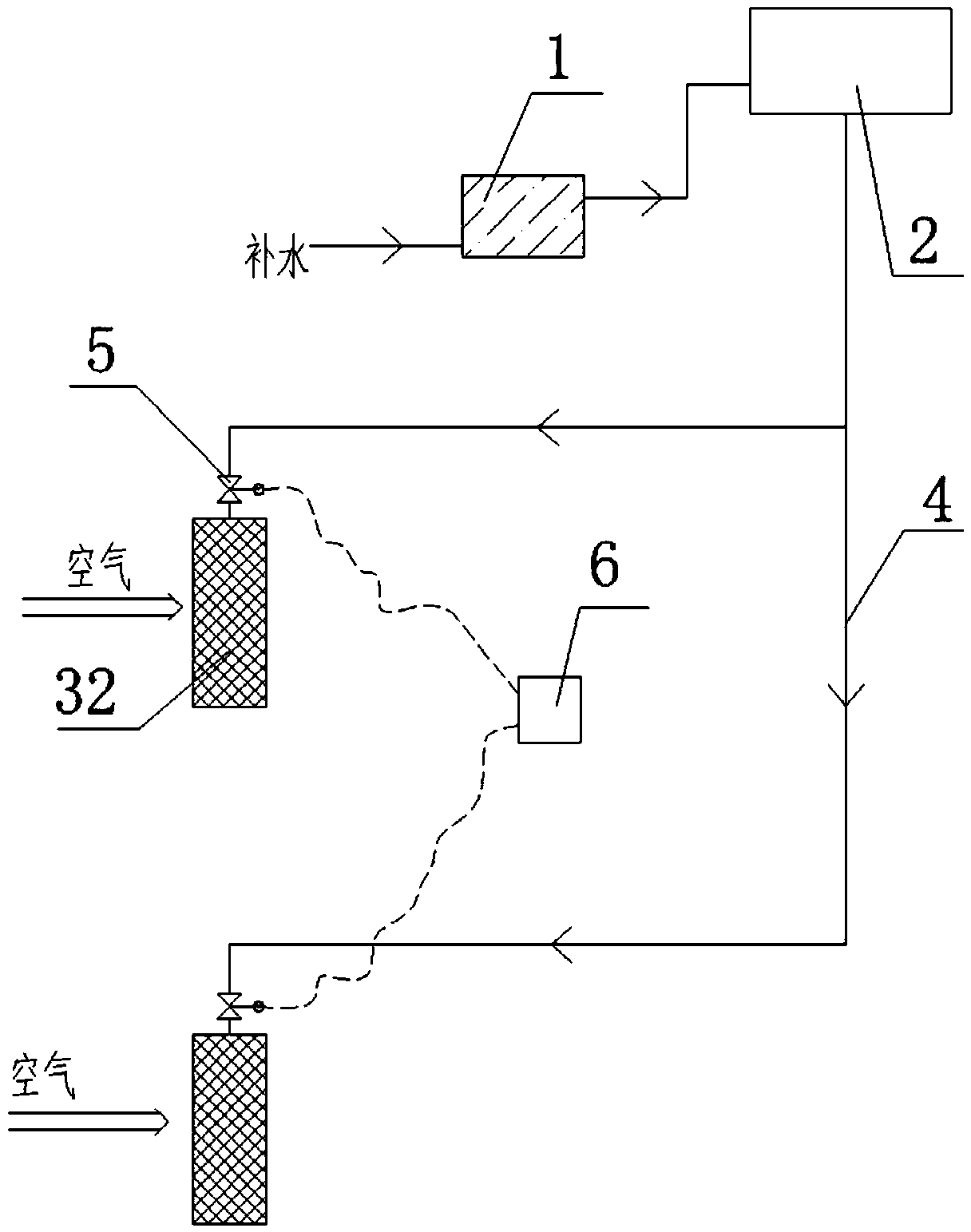
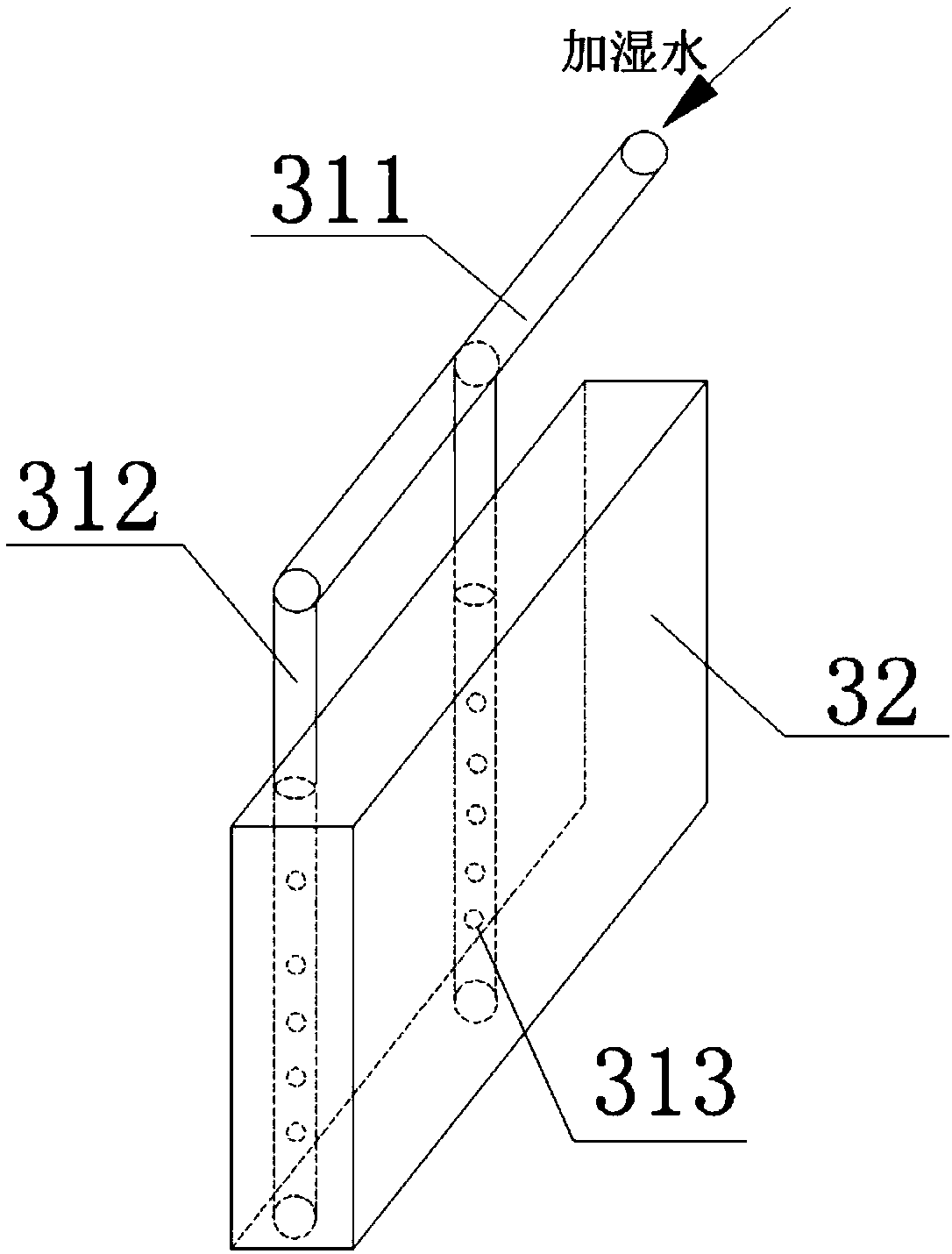
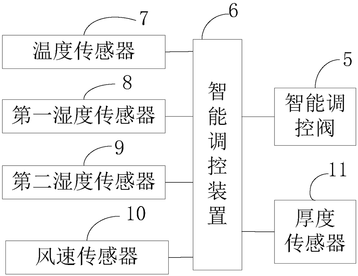
The invention discloses a powerless solar humidification system and method. The powerless solar humidification system comprises a solar heat collector arranged outdoors, a heat collecting water tank with the physical height larger than the height of the solar heat collector, and one or more wet film humidifiers with the physical height smaller than the height of the heat collecting water tank. A water outlet of the heat collecting water tank is connected with water inlets of the wet film humidifiers through pipelines. Each pipeline comprises an intelligent humidification amount regulation andcontrol valve, wherein an intelligent regulation and control valve can automatically adjust the valve aperture of the intelligent regulation and control valve according to the moisture content of outdoor air and indoor air and the water temperature in the heat collecting water tank, and the humidification water volume is adjusted. At least one air conditioner draught fan and / or a fresh air draughtfan are / is further included, wherein an air outlet of the draught fan faces a wet film, and air blown out of the draught fan is blown out with water after passing through the wet film. In the whole heat collecting, hot water storing and conveying and air humidifying process, under the action of solar energy, heat expansion and cold shrinkage and gravity, energy consumption equipment does not exist, and energy is not consumed. Compared with a traditional humidification manner, the humidification system saves more energy and water, and the humidification effect is more obvious.

Description

technical field [0001] The invention relates to a humidification system, in particular to a non-powered solar humidification system and method. Background technique [0002] In northern China, the indoor air in winter is relatively dry, and humidification is often required to meet the comfortable humidity requirements of indoor air (generally greater than 30%). The currently used humidification methods are wet film, dry steam, electric heating or ultrasonic humidification. Humidification by dry steam or electric heating often consumes a large amount of electric energy or heat energy, and the operating cost is high. The method of using wet film is to directly pour tap water on the wet film. Because the temperature of tap water is low in winter, the humidification effect is not good. It is not ideal, and the water consumption is high. In order to improve the humidification effect, the temperature of the fresh air is often raised to 50°C or higher before humidification. This m...

Claims


Application Information

Patent Timeline
IPC IPC(8): F24F6/04F24F11/89F24F11/74F24F11/64F24S20/00F24S80/00F24F110/20F24F110/22F24F110/10
CPCF24F6/04F24F11/64F24F11/74F24F11/89F24F2110/10F24F2110/20F24F2110/22Y02E10/40
Inventor 居发礼
Owner 重庆山那里环境科技有限公司
Learn More