An automatic cloth device with a narrow space in a vertical plane
A narrow space, vertical surface technology, applied in the field of automatic patch device, can solve the problems of increasing the cost of radiation detection and affecting the efficiency of radiation detection
- Summary
- Abstract
- Description
- Claims
- Application Information
AI Technical Summary
Problems solved by technology
Method used
Image

Examples
Embodiment 1
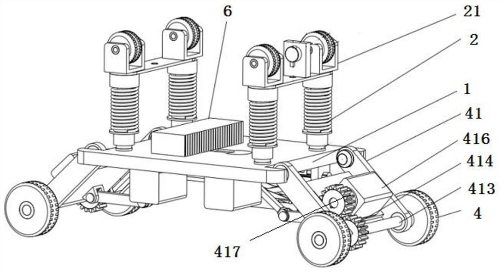
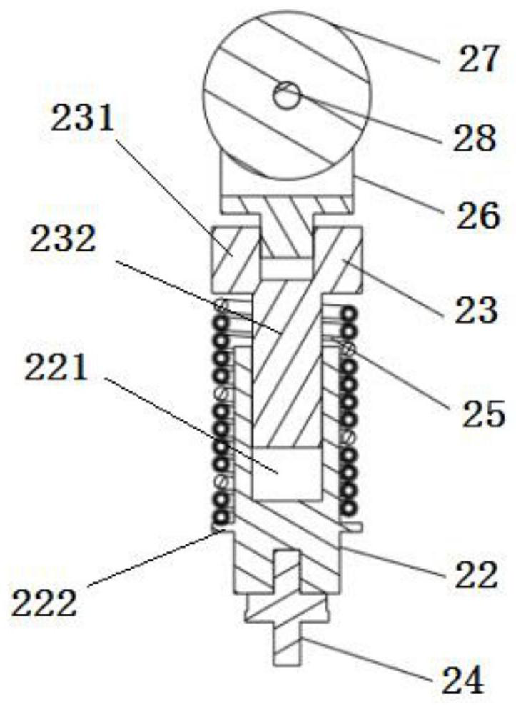
[0023] In this example, see figure 1 , the heavy-duty pressure sensing mechanism 2 includes support mechanisms 21 arranged at the four corners of the top surface of the frame 1, combined with image 3 , the support mechanism 21 includes a spring support plate 22, a heavy pressure sensor 23 is provided between the bottom surface of the spring support plate 22 and the frame 1, and a guide shaft 24 is provided on the spring support plate 22, and the guide shaft 24 includes a shaft head 241 and a shaft rod 242, the shaft rod 242 fits in the guide shaft hole 221 provided at the upper end of the spring support plate 22, and has the freedom to reciprocate along the guide shaft hole 221, the shaft head 241 is limited above the guide shaft hole 221, and the spring support plate The outer wall of 22 is provided with a spring limit step 222, and the spring 25 is sleeved on the spring support plate 22 and the shaft rod 242 between the spring limit step 222 and the shaft head 241, and the ...
Embodiment 2
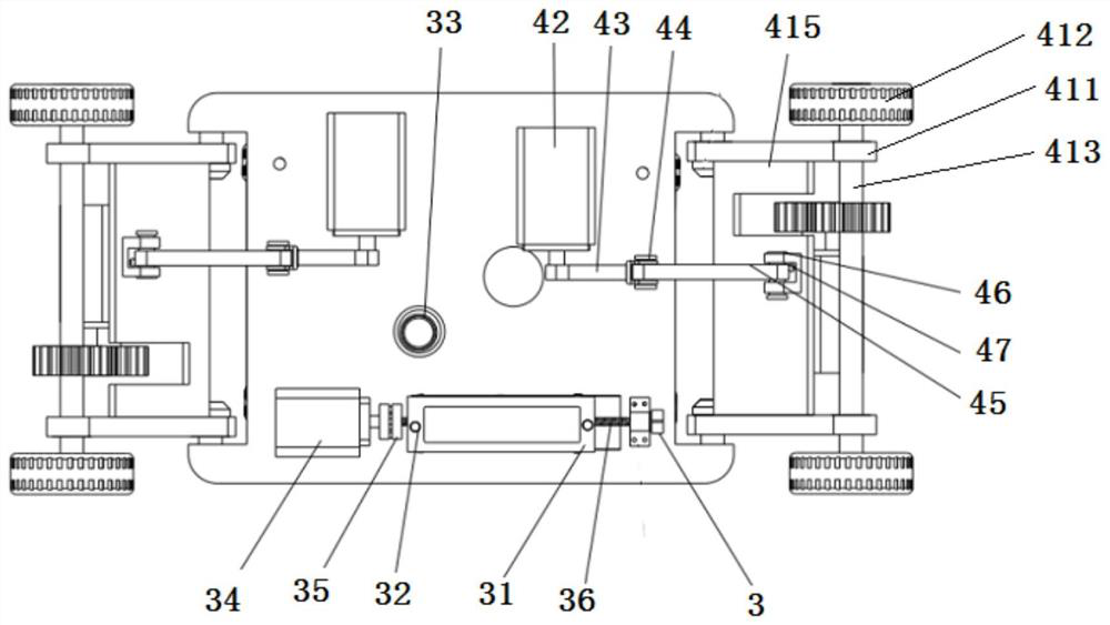
[0027] In this example, see figure 2 and Figure 4 The placement mechanism 3 includes a positioner 33 and a placement motor 34, the positioner 33 is connected to the signal of the controller 6, the signal of the controller 6 is connected to the placement motor 34, and the output shaft of the placement motor 34 passes through the shaft coupling 35 A lead screw 36 is coaxially connected, and a ball screw pair 37 is set on the lead screw 36. The ball screw pair 37 is fixed to the bottom end of the lift link 38, and the patch support plate 31 is fixed to the upper end of the lift link 38. A lightweight pressure sensor 32 is located on the surface of the patch support plate 31 .
[0028] During use, locator 3 (invisible in space, can adopt night vision camera) finds the position required for filming, and controller 6 starts patch motor 34, drives leading screw 36, adjusts the height of elevating link 38, when patch support plate When the film on 31 is pasted on the inner wall of...
Embodiment 3
[0031] In this example, see figure 1 and figure 2The crawling mechanism 4 includes a rotating motor 42 connected with the controller 6 signals, the rotating motor 42 is symmetrically arranged on both sides of the bottom surface of the frame 1, the output shaft of the rotating motor 42 is connected with one end of the crank rocker 43, and the crank rocker 43 The other end is connected with the rocking bar 45 by the pin I44, and the other end of the rocking bar 45 is connected with the hinged end of the hinge bracket 47 by the pin II46. A crawling wheel 412 is provided, and the crawling wheels 412 on the same side are connected by a connecting shaft 413. The connecting shaft 413 is provided with a driven gear 414, and a crawling motor support plate 415 is provided between the swing rods 411 on the same side, and the crawling motor supports Plate 415 front is provided with the creeping motor 416 that is connected with controller 6 signals, and the output shaft of crawling motor...
PUM
 Abstract
Description
Claims
Application Information
 - R&D
- Intellectual Property
- Life Sciences
- Materials
- Tech Scout
- Unparalleled Data Quality
- Higher Quality Content
- 60% Fewer Hallucinations
Browse by: Latest US Patents, China's latest patents, Technical Efficacy Thesaurus, Application Domain, Technology Topic, Popular Technical Reports.
© 2025 PatSnap. All rights reserved.Legal|Privacy policy|Modern Slavery Act Transparency Statement|Sitemap|About US| Contact US: help@patsnap.com