
Anti-freezing liquid tank, anti-freezing liquid tank system and anti-freezing method

An anti-coagulation and liquid tank technology, used in the field of anti-coagulation, anti-coagulation liquid tanks, and anti-coagulation liquid tank systems, can solve problems such as user inconvenience, affecting cleaning or coating quality, and achieve the effect of preventing liquid coagulation.

Active Publication Date: 2020-04-03
BEIJING INST OF RADIO MEASUREMENT
View PDF5 Cites 0 Cited by
  • Summary
  • Abstract
  • Description
  • Claims
  • Application Information

AI Technical Summary

Problems solved by technology

When cleaning or coating the workpiece, if the liquid in the liquid tank is easy to volatilize and solidify and the liquid tank cannot be sealed, especially when there is an air knife or other device near the liquid tank that is likely to cause air flow around the liquid tank, the liquid The liquid in the tank is easy to solidify on the surface to form a thin film, and it may dry out directly in the liquid tank after a long time, seriously affecting the quality of subsequent cleaning or coating, and causing inconvenience to users

Method used


Image

  • Anti-freezing liquid tank, anti-freezing liquid tank system and anti-freezing method
  • Anti-freezing liquid tank, anti-freezing liquid tank system and anti-freezing method
  • Anti-freezing liquid tank, anti-freezing liquid tank system and anti-freezing method

Examples


Embodiment 1

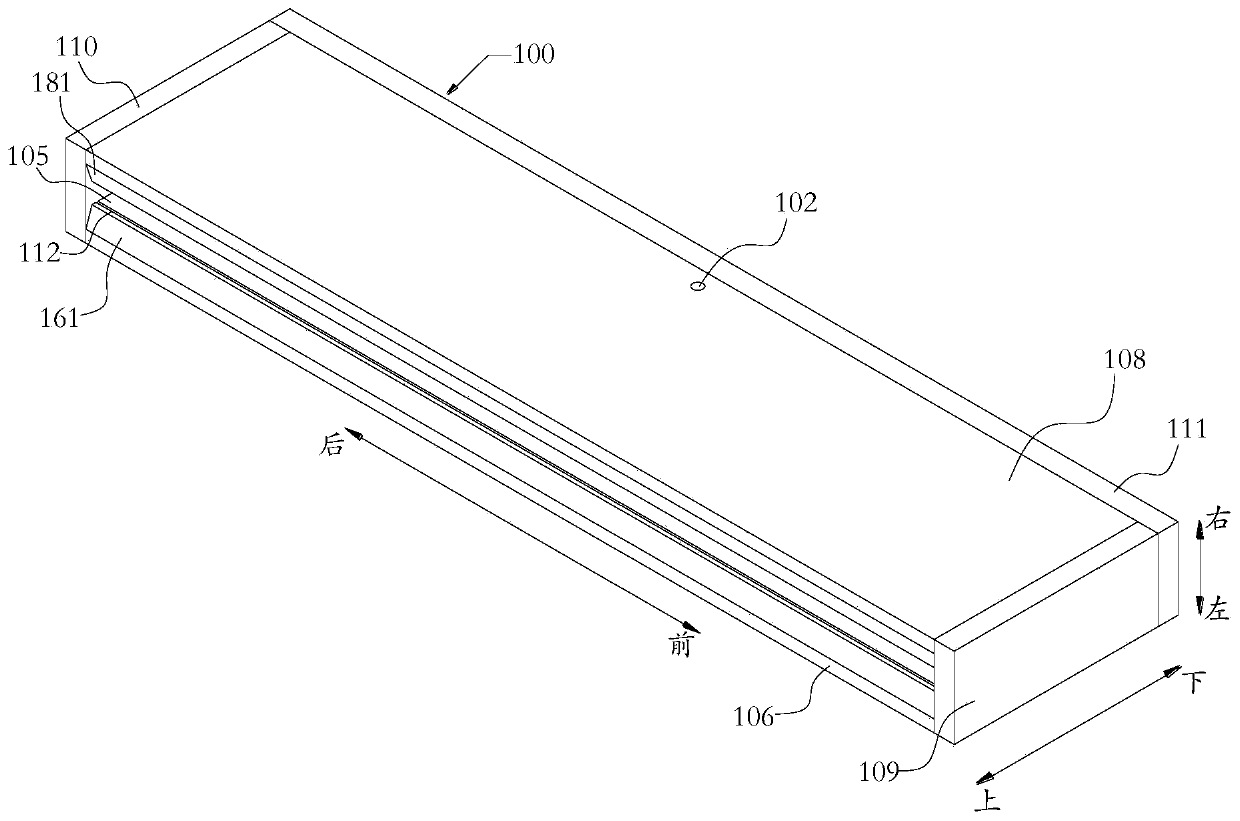
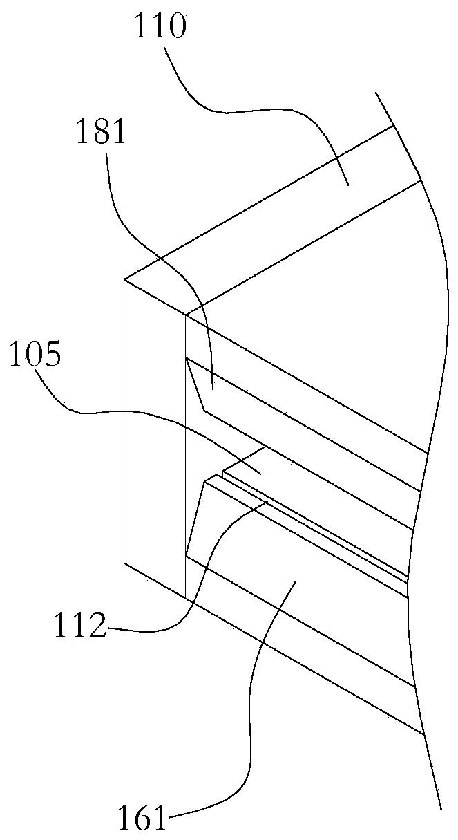
[0052] Such as Figure 1-Figure 8 As shown, in the anti-freezing liquid tank of this embodiment, the bottom of the liquid tank 100 is provided with a liquid outlet 101, and the position of the side wall of the liquid tank 100 is provided with a liquid inlet 102; 100 is formed with a liquid inlet chamber 103, a liquid storage chamber 114 and a liquid outlet chamber 104, the upper end of the liquid storage chamber 114 is open to communicate with the outside world, the lower end of the liquid storage chamber 114 communicates with the liquid outlet chamber 104, The lower end of the liquid outlet chamber 104 communicates with the liquid outlet 101 ; the upper end of the liquid inlet chamber 103 communicates with the upper end of the liquid storage chamber 114 , and the lower end of the liquid inlet chamber 103 communicates with the liquid inlet 102 .

[0053] In this embodiment, the number of liquid inlets and liquid outlets in the liquid tank 100 can be set according to actual nee...

Embodiment 2

[0056] Such as Figure 1-Figure 8 As shown, in addition to the technical features of Embodiment 1, this embodiment further defines the structures of the liquid inlet chamber 103, the liquid storage chamber 114, and the liquid outlet chamber 104, as follows.

[0057] Such as Figure 4-Figure 8 As shown, the liquid inlet chamber 103 in this embodiment includes an upper liquid inlet buffer chamber 131, several liquid inlet channels 132, and a lower liquid inlet buffer chamber 133 arranged in sequence from top to bottom, and several of the liquid inlet channels 132 are arranged vertically side by side. Arranged and independent of each other; the upper ends of several of the liquid inlet channels 132 are in communication with the upper liquid inlet buffer chamber 131, and the lower ends are in communication with the lower liquid inlet buffer chamber 133; the liquid inlet 101 is connected with the lower liquid inlet The buffer chamber 133 is in communication, and the upper inlet bu...

Embodiment 3

[0067] Such as Figure 9 As shown, an anti-freezing liquid tank system in this embodiment includes the liquid tank 100, the liquid tank circulating pump 200 and the circulating liquid storage barrel 300, and the liquid outlet 101 at the bottom of the liquid tank 100 is connected to the liquid tank through a pipeline. The circulating liquid storage tank 300 is connected and the liquid in the liquid tank 100 is input into the circulating liquid storage tank 300, and the liquid inlet on the side wall of the liquid tank 100 is connected with the circulating liquid storage tank 300 through a pipeline. connected, the liquid tank circulating pump 200 is installed on the pipeline between the liquid inlet 102 and the circulating liquid storage barrel 300 and the liquid in the circulating liquid storing barrel 300 is input into the liquid tank 100 . There is a one-to-two three-way valve at the outlet of the circulating liquid storage pump 200, which divides the liquid into two pipeline...


PUM


Abstract

The invention relates to an anti-coagulation liquid tank, an anti-coagulation liquid tank system and an anti-coagulation method. A liquid outlet is provided at the bottom of the liquid tank, and a liquid inlet is provided at the position lower than the side wall of the liquid tank; Liquid chamber, liquid storage chamber and liquid outlet chamber, the upper end of the liquid storage chamber is open to communicate with the outside world, the lower end of the liquid storage chamber is connected with the liquid outlet chamber, the lower end of the liquid outlet chamber is connected with the liquid outlet; the upper end of the liquid inlet chamber is connected with the liquid storage chamber The upper end of the chamber is connected, and the lower end of the liquid inlet chamber is connected with the liquid inlet. In the anti-freezing liquid tank of the present invention, the liquid flows through the liquid inlet chamber from bottom to top into the liquid storage chamber, and then flows through the liquid outlet chamber from top to bottom, so that the liquid continues to circulate in the liquid tank, and the liquid is not easy to freeze; and the present invention The upper end of the liquid storage chamber of the invented liquid tank is an open structure. After the liquid tank is combined with the external circulation operation, for cleaning liquid or coating liquid with high viscosity or easy to solidify, and the liquid tank cannot be cleaned or coated during the cleaning or coating process. In the case of airtight treatment, the liquid in the liquid tank can still be effectively prevented from solidifying.

Description

technical field [0001] The invention relates to cleaning equipment or coating equipment in the field of mechanical equipment, in particular to an anti-coagulation liquid tank, an anti-coagulation liquid tank system and an anti-coagulation method for preventing liquid from solidifying in the liquid tank during cleaning or coating operations. Background technique [0002] Cleaning or coating workpieces is a widely used operation in the semiconductor industry and its related industrial production industries. When cleaning or coating the workpiece, if the liquid in the liquid tank is easy to volatilize and solidify and the liquid tank cannot be sealed, especially when there is an air knife or other device near the liquid tank that is likely to cause air flow around the liquid tank, the liquid The liquid in the tank is easy to solidify on the surface to form a thin film, and it may dry out directly in the liquid tank after a long time, seriously affecting the quality of subsequen...

Claims


Application Information

Patent Timeline
Patent Type & Authority Patents(China)
IPC IPC(8): B08B3/08B08B13/00B05C11/11B05C11/10
CPCB05C11/10B05C11/11B08B3/08B08B13/00
Inventor 陈伟彭文武陆岩
Owner BEIJING INST OF RADIO MEASUREMENT
Learn More