Efficient liquid medicine stirring device
A technology for mixing and mixing liquid medicine, which is applied to mixers, mixers, mixer accessories and other directions with rotating mixing devices, which can solve the problems of difficulty in changing the rotation direction of mixers, and achieve stability protection, sufficient mixing, and enhanced mixing. The effect of efficiency
- Summary
- Abstract
- Description
- Claims
- Application Information
AI Technical Summary
Problems solved by technology
Method used
Image

Examples
Embodiment 1
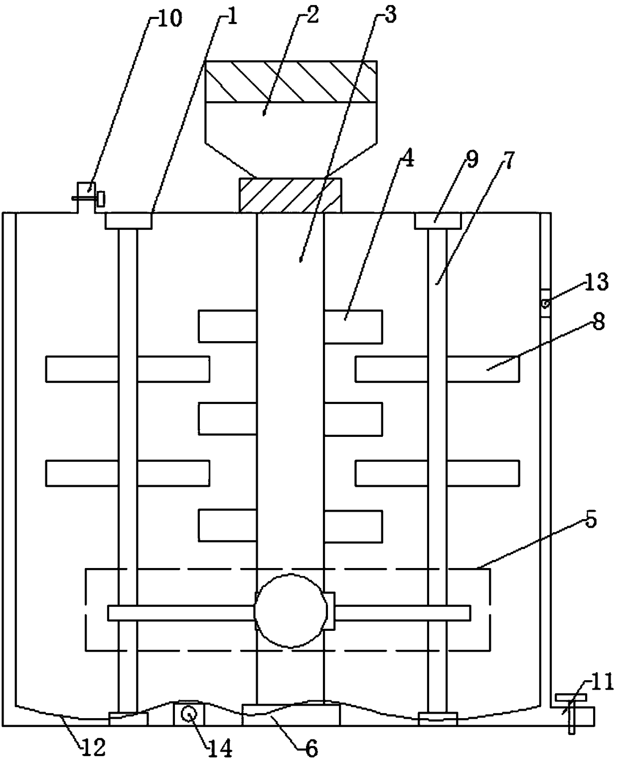
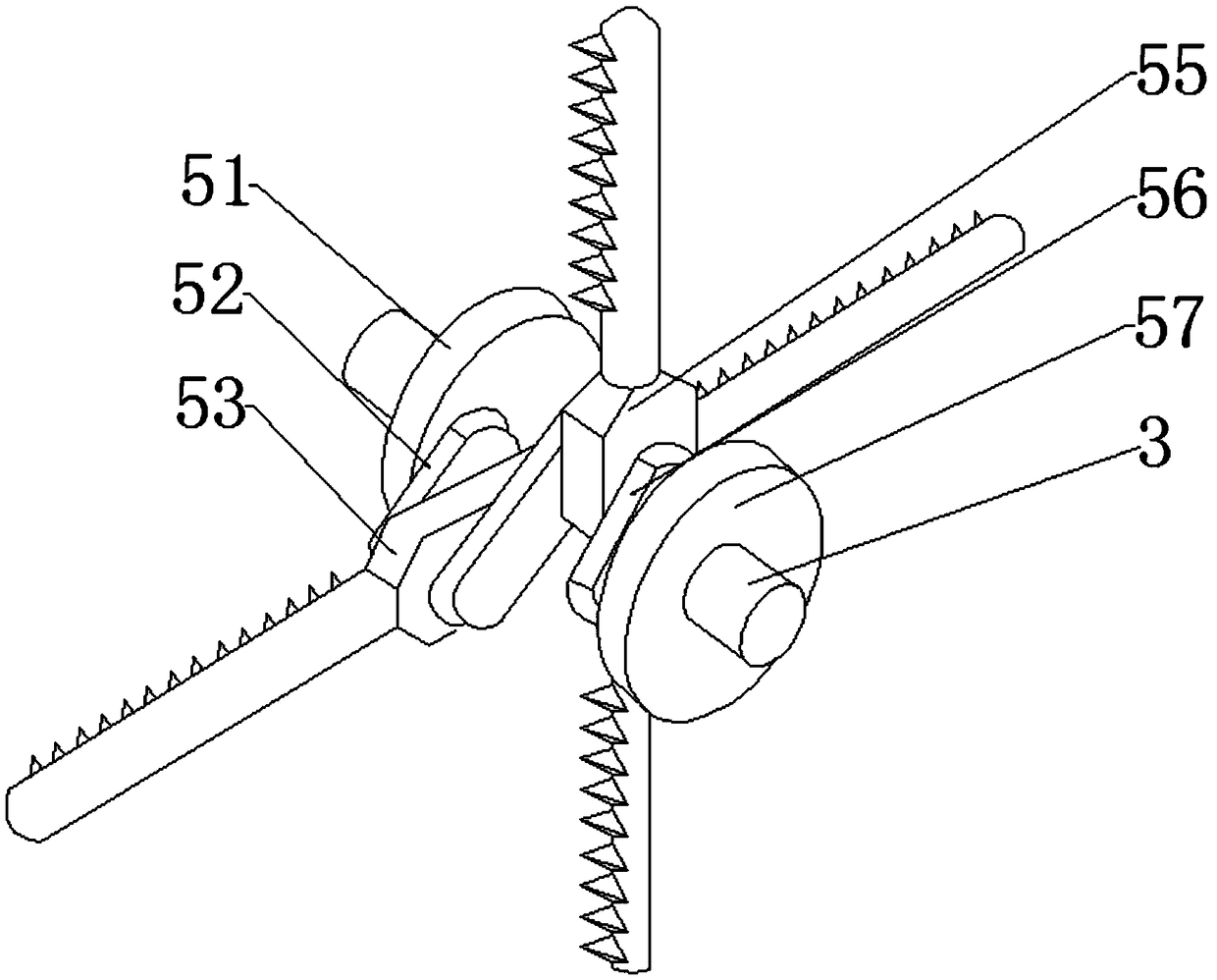
[0031] A high-efficiency liquid medicine stirring and mixing device, comprising a mixing tank, the top and bottom of the mixing tank are respectively provided with a liquid inlet and a liquid outlet, the mixing tank is provided with a driving motor, and the output shaft of the driving motor is provided with a first stirring tank. A crankshaft reciprocating assembly is connected between the two output shafts of the drive motor. The crankshaft reciprocating assembly includes a first connecting block, a second connecting block, and a third connecting block arranged in sequence along the axial direction of the output shaft. The first connecting block One end of one of the output shafts is eccentrically hinged, the other end of the first connecting block is hinged to the second connecting block through the first hinge shaft, and the first reciprocating connecting rod is sleeved on the first hinge shaft, and the second connecting block The other end of the third connection block is h...
Embodiment 2
[0033] On the basis of Embodiment 1, the crankshaft reciprocating assembly is also covered with a protective shell, the first reciprocating connecting rod and the second reciprocating connecting rod are all set through the protective shell and the first reciprocating connecting rod can be the length of the first reciprocating connecting rod The direction slides on the protective shell, and the second reciprocating link can slide on the protective shell along the length direction of the second reciprocating link. By setting the protective shell, on the one hand, the protective shell forms a certain protective effect on the stability of the crankshaft reciprocating assembly, and on the other hand forms a limiting effect on the first reciprocating connecting rod and the second reciprocating connecting rod, so that the first reciprocating connecting rod and the second reciprocating connecting rod The two reciprocating connecting rods work stably and normally on their fixed motion t...
Embodiment 3
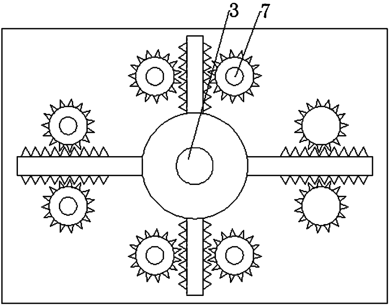
[0035] On the basis of the above embodiments, the output shaft of the drive motor includes a first output shaft directly connected to the drive motor and a second output shaft far away from the drive motor, the output end of the first output shaft is connected with a first round One end of the first connecting block is eccentrically hinged on the first round wheel; one end of the second output shaft is connected to the second round wheel, one end of the third connecting block is eccentrically hinged on the second round wheel, and the second output shaft The other end is fixed on the bottom of the mixing bucket through a bearing. Set round wheels at the ends of the two output shafts respectively, avoiding the too small inner diameter of the output shaft, which makes the swing range of the crankshaft back pressure assembly too small; set appropriate round wheels, and eccentrically connect the first connecting block, The third connection block helps to improve the mixing efficien...
PUM
 Abstract
Description
Claims
Application Information
 - Generate Ideas
- Intellectual Property
- Life Sciences
- Materials
- Tech Scout
- Unparalleled Data Quality
- Higher Quality Content
- 60% Fewer Hallucinations
Browse by: Latest US Patents, China's latest patents, Technical Efficacy Thesaurus, Application Domain, Technology Topic, Popular Technical Reports.
© 2025 PatSnap. All rights reserved.Legal|Privacy policy|Modern Slavery Act Transparency Statement|Sitemap|About US| Contact US: help@patsnap.com