Bed board turning assisting device of nursing sickbed

A technology of flipping device and bed board, which is applied to hospital beds, medical science, hospital equipment, etc., can solve the problems of troublesome handling of patients and the inability to transfer patients at will on temporary beds, so as to achieve stable and reliable clamping, easy to manufacture and use together, and to meet the needs of The effect of functional requirements

Inactive Publication Date: 2018-10-12
XUCHANG UNIV
View PDF6 Cites 1 Cited by
  • Summary
  • Abstract
  • Description
  • Claims
  • Application Information

AI Technical Summary

Problems solved by technology

[0004] The present invention aims at the troublesome handling operation of the patient during the examination of the critically ill patient and the problem that the existing temporary hospital bed cannot transfer th...

Method used


Image

  • Bed board turning assisting device of nursing sickbed
  • Bed board turning assisting device of nursing sickbed
  • Bed board turning assisting device of nursing sickbed

Examples


Embodiment 1

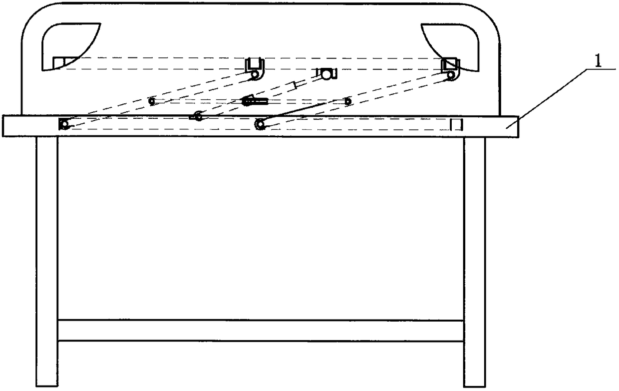
[0019] Embodiment 1: as figure 1 In the bed board power-assisted turning device shown, the bed board of the hospital bed is designed as a movable bed board 3 and by means of the driving function of the power-assisted turning frame, the burden on the nursing staff and the difficulty of operation can be reduced.

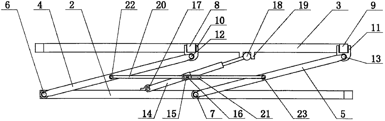
[0020] like Figure 2-Figure 4 As shown, the power-assisted turning frame includes a fixed seat 2, a front swing link 4 and a rear swing link 5, and structural components such as a booster cylinder 14. Wherein, the fixed seat 2 is two fixed components, which are fixed on the bed body ends at the two ends of the movable bed board 3 respectively, and can be installed with the existing sick bed, or a special sick bed and the fixed seat 2 can be installed together. A front swing link 4 and a rear swing link 5 are respectively arranged at both ends of the movable bed board 3 . The lower end of the front swing link 4 on each side is hinged at the front end of the fixed sea...

Embodiment 2

[0024] Embodiment 2: On the basis of Embodiment 1, a linkage structure is provided between the front swing link 4 and the rear swing link 5 on each side to improve its stability and linkage, and the operation is simple and convenient. Specifically, pin one and pin two are respectively arranged on the front swing link 4 and the rear swing link 5, and a linkage rod 20 is hinged on the pin one and pin two.

Embodiment 3

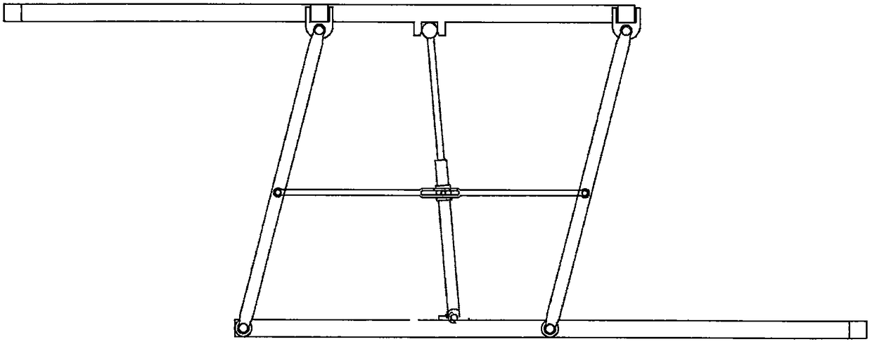
[0025] Embodiment 3: On the basis of Embodiment 2, a linkage relationship is added to the booster cylinder 14 . During the swinging process of the front swing link 4 and the rear swing link 5, the booster cylinder 14 is not parallel to the front swing link 4 or the rear swing link 5. If a linkage relationship is added to the booster cylinder 14, the relationship between the linkage lever 20 and the booster cylinder 14 needs to be considered. slippage between cylinders. For details, see Figure 1-Figure 3 As shown, a sliding sleeve 15 is set on the outside of the cylinder body of the booster cylinder 14, and a sliding column 16 is vertically fixed on the side of the sliding sleeve 15. At the same time, a chute 21 is arranged in the middle of the linkage rod 20, and the sliding column 16 is matched with the chute. 21 in.


PUM


Abstract

The invention discloses a bed board turning assisting device of a nursing sickbed. A fixed seat is fixed to the end of a bed body at two ends of a movable bed board; the lower ends of swing rods at two ends of the movable bed board are hinged on the fixed seat via front fixed rotating shafts; a front clamping pillar and a rear clamping pillar are arranged in the middle and at the back of two endsof the movable bed board; a front clamping seat is clamped at the lower side of the front clamping pillar, and a rear clamping seat is clamped at the lower side of the rear clamping pillar; and an assisting air cylinder is each arranged at two sides of the movable bed board. According to the turning assisting device provided by the invention, a patient on the sickbed can be rapidly transferred onto a detection equipment platform and the patient on the detection equipment platform can be transferred onto the sickbed. Under the actions of swinging and the assisting air cylinders, the patient canbe transferred by one person. The turning assisting device is simple to use, easy for manufacturing and cooperated use and suitable for promotion and application.

Description

Technical field: [0001] The invention belongs to the technical field of hospital nursing auxiliary equipment, and in particular relates to a nursing bed board power-assisted turning device. Background technique: [0002] In the prior art, the improvement of the hospital bed is mostly reflected in the turning function. For example, it generally has the function of turning the front part. The lifting mechanism is driven by the rocker at the tail of the bed to realize the raising or lowering of the front part of the bed, thereby raising the head of the human body. and chest. And the design of flipping left and right. However, when examining a seriously ill patient, in many cases where the mobile testing equipment cannot be moved, the patient needs to be transferred to the testing equipment platform together with the hospital bed. Due to the high frequency of use of the detection equipment, it is usually necessary to wait in line. For the detection of seriously ill patients, t...

Claims


Application Information

Patent Timeline
IPC IPC(8): A61G7/057A61G7/05
CPCA61G7/001A61G7/05
Inventor 王晓冰魏渊博郗磊磊
Owner XUCHANG UNIV
Why Eureka
Try Eureka