
Stator punching plate, stator assembly and motor

A technology for stator punching and stator assembly, applied in electrical components, electromechanical devices, electric components, etc., can solve the problems of high cost of materials and low effective utilization of windings, and achieve weight reduction, saving of winding materials, and effective utilization of rate increase effect

Active Publication Date: 2018-10-09
GUANGDONG WELLING ELECTRIC MACHINE MFG
View PDF5 Cites 2 Cited by
  • Summary
  • Abstract
  • Description
  • Claims
  • Application Information

AI Technical Summary

Problems solved by technology

[0004] The purpose of the present invention is to overcome the problems of the prior art such as the labor cost of the stator winding, the high material cost and the low effective utilization rate of the winding.

Method used


Image

  • Stator punching plate, stator assembly and motor
  • Stator punching plate, stator assembly and motor
  • Stator punching plate, stator assembly and motor

Examples


Embodiment Construction

[0030] Specific embodiments of the present invention will be described in detail below in conjunction with the accompanying drawings. It should be understood that the specific embodiments described here are only used to illustrate and explain the present invention, and are not intended to limit the present invention.

[0031] It should be noted that, in the case of no conflict, the embodiments and features in the embodiments of the present invention can be combined with each other.

[0032] In describing the present invention, it should be understood that the terms "center", "longitudinal", "transverse", "length", "width", "thickness", "upper", "lower", "left", " The orientation or positional relationship indicated by "right", "vertical", "horizontal", "top", "bottom", "axial", "radial", "circumferential" etc. is based on the orientation or position shown in the drawings The positional relationship is only for the convenience of describing the present invention and simplifyin...


PUM


Abstract

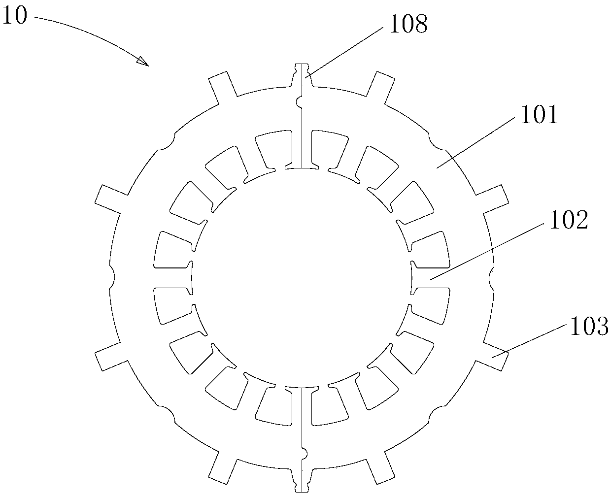
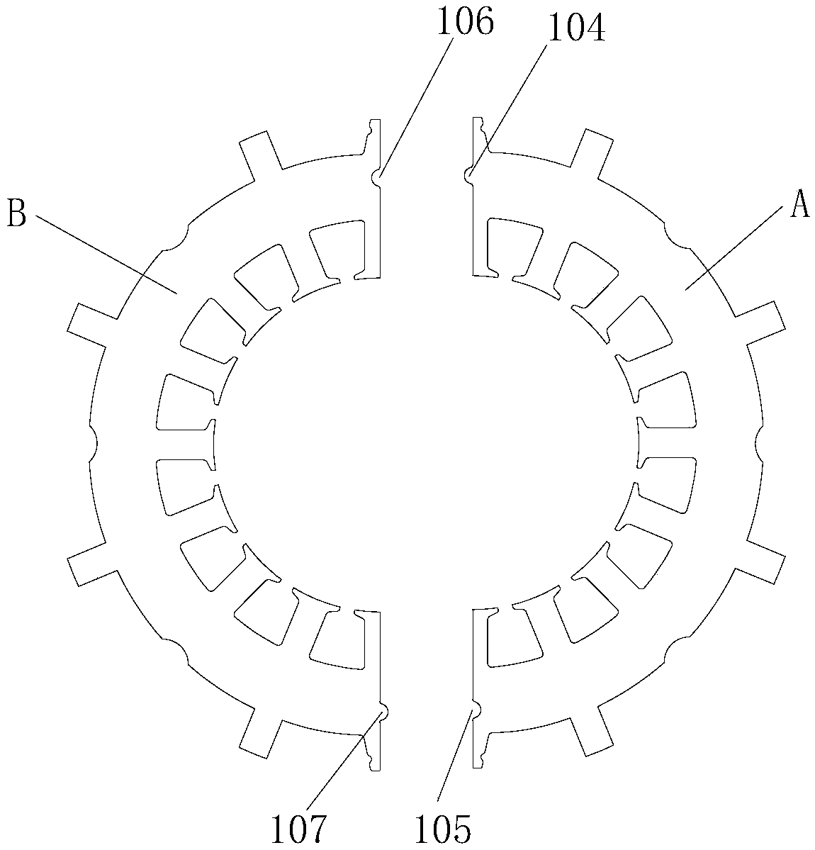
The invention discloses a stator punching plate, a stator assembly and a motor. The stator punching plate includes a yoke part (101) and a plurality of teeth (102) arranged on the yoke part (101) along the inner periphery at intervals. The state punching plate is characterized in that the outer periphery of the yoke part (101) is provided with a plurality of bosses (103) used for fitting positioning with a housing of the motor at intervals. According to the invention, the effective utilization rate of windings can be improved effectively and material of the windings can be saved and the weightof the windings can be reduced. Besides, implementation of automation can be facilitated, production efficiency of the motor can be improved and labor cost can be saved.

Description

technical field [0001] The invention relates to the technical field of motors, in particular to a stator punch, a stator assembly and a motor. Background technique [0002] At present, the winding of the traditional AC motor usually adopts the distributed winding method. [0003] However, in traditional distributed winding stator drop, it is first necessary to manually drop the winding into the designed mold, and then through the mold, the winding is dropped into the slot of the stator core. The fall-off method of the stator winding requires a large number of front-line employees on the stator assembly production line, resulting in high labor costs for a single motor. In addition, the traditional winding method of the stator winding requires a large amount of winding wire, which leads to a low effective utilization rate of the winding, and increases the material cost and the weight of the winding. Contents of the invention [0004] The purpose of the invention is to over...

Claims


Application Information

Patent Timeline
Patent Type & Authority Applications(China)
IPC IPC(8): H02K1/14
CPCH02K1/148
Inventor 洪海生王兴智李祖荣张维
Owner GUANGDONG WELLING ELECTRIC MACHINE MFG
Learn More