
Non-contact charging system

A non-contact charging and non-contact technology, applied in charging stations, electric vehicle charging technology, electric vehicles, etc., can solve problems such as removing obstacles, and achieve the effect of saving labor and time

Active Publication Date: 2018-10-09
HONDA MOTOR CO LTD
View PDF7 Cites 0 Cited by
  • Summary
  • Abstract
  • Description
  • Claims
  • Application Information

AI Technical Summary

Problems solved by technology

However, if it is not the case that the person who started the non-contact power transmission or the person who can control the non-contact power transmission is not present, there is no way for other people (third parties) to easily remove the obstacle without being affected by the magnetic field. Effects of Exposure

Method used


Image

  • Non-contact charging system
  • Non-contact charging system
  • Non-contact charging system

Examples


Embodiment Construction

[0049] Hereinafter, embodiments of the present invention will be described with reference to the drawings. It should be noted that the drawings are viewed along the direction of the symbols. In the following description, front and rear, left and right, and up and down are in accordance with the directions observed by the driver. In the drawings, the front of the vehicle is represented as Fr, and the rear is represented as Rr , The left side is represented by L, the right side is represented by R, the top is represented by U, and the bottom is represented by D.

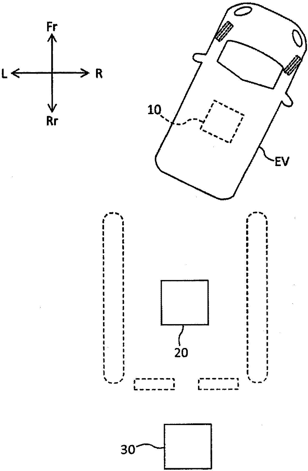
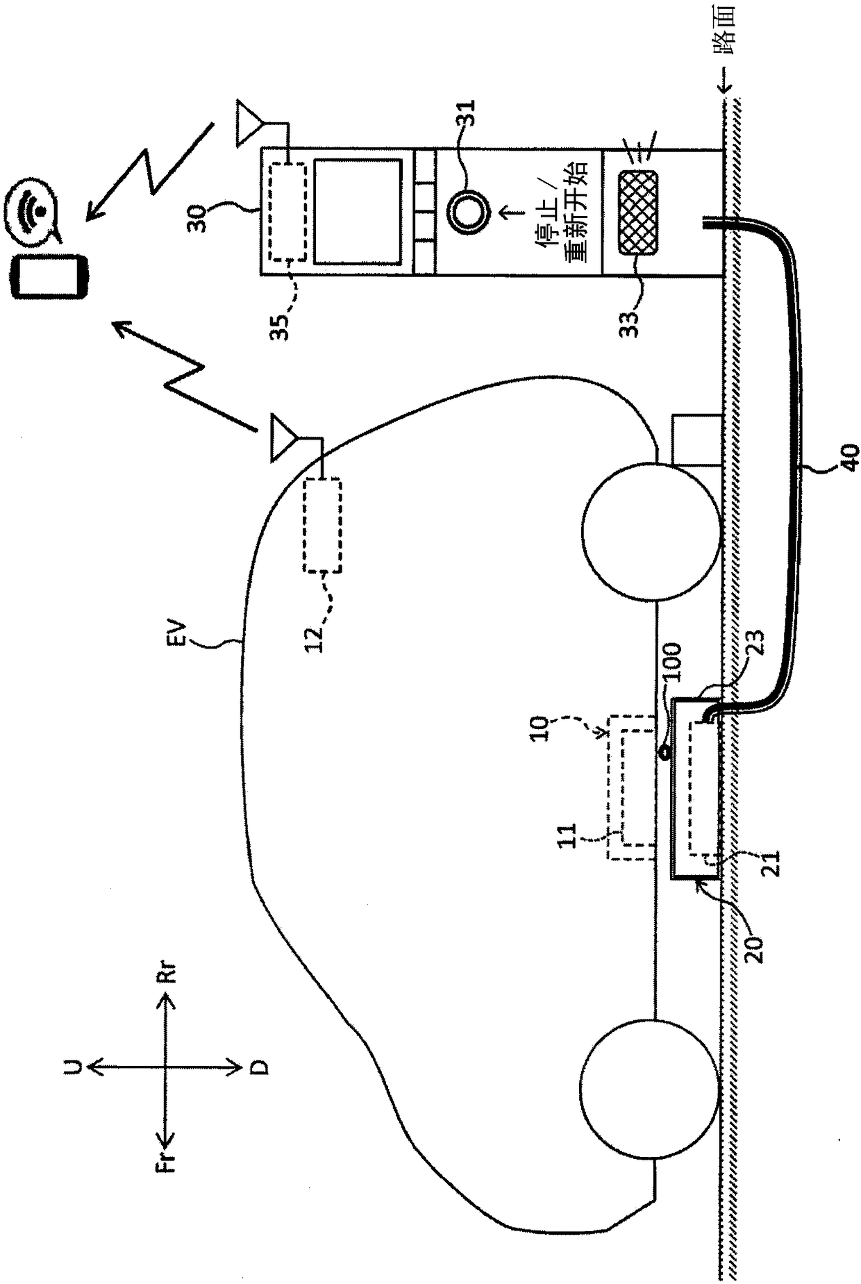
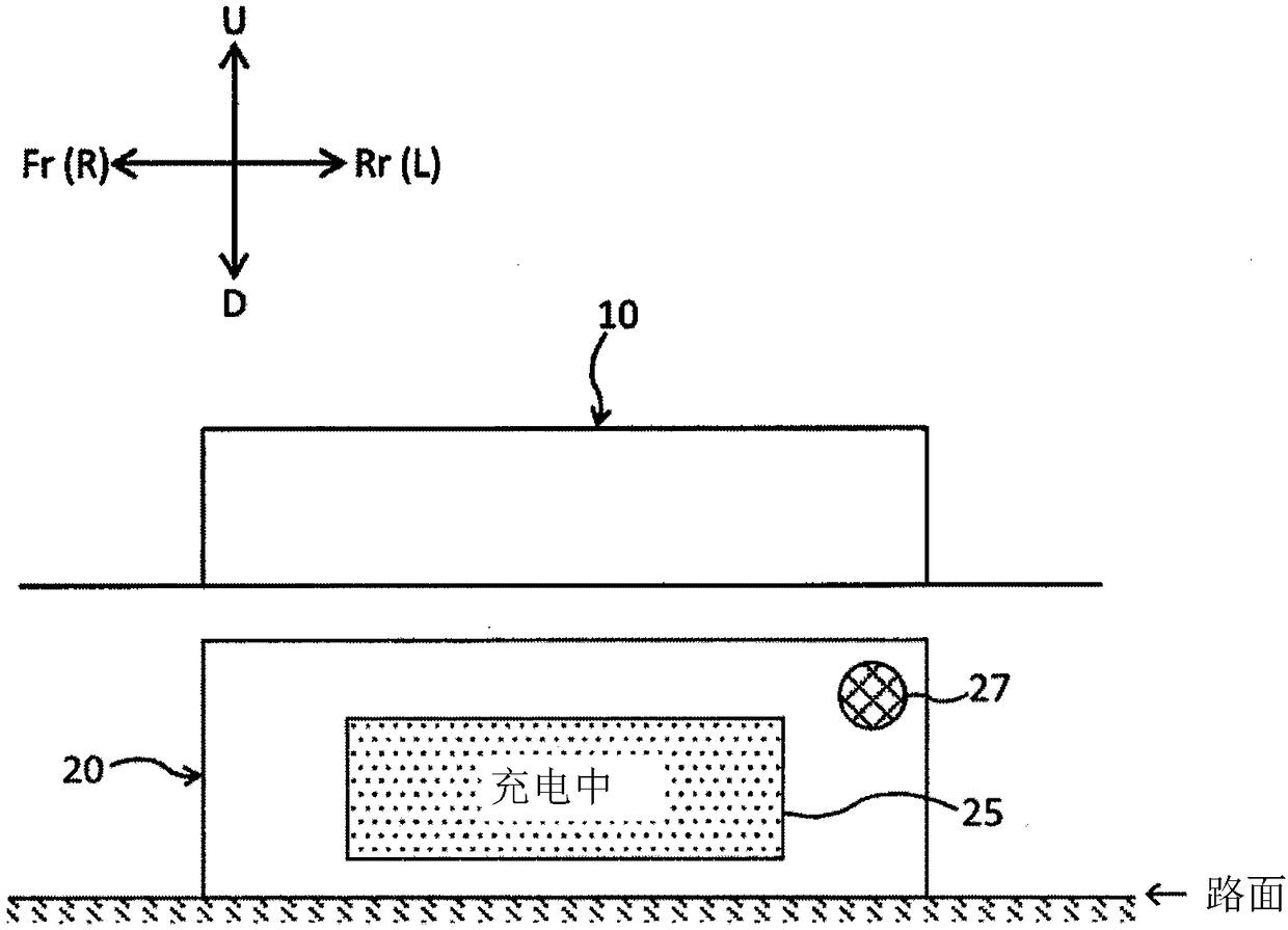
[0050] figure 1 It is a plan view showing a state in which the electric vehicle is parked in the middle of a parking position where the power transmission device is arranged. figure 2 It is a side view showing a state where an electric vehicle is parked at a parking position where a power transmission device is arranged. Such as figure 1 and figure 2 As shown, the power transmission device 20 arranged at the park...


PUM


Abstract

The invention provides a non-contact charging system enabling a third party as well as a specific person to take a precautionary measure against magnetic field exposure and then to remove an obstaclebetween a power transmission unit and a power receiving unit. The non-contact charging system includes: a power receiving unit mounted on a transportation device; a power transmission unit, installedon a flat surface, configured to transmit power to the power receiving unit in a non-contact manner; and a power supply unit configured to control power supply to the power transmission unit, the power supply unit including an operation portion configured to temporarily stop or resume non-contact power transmission from the power transmission unit to the power receiving unit.

Description

technical field [0001] The present invention relates to a non-contact charging system utilizing a non-contact power transmission technology. Background technique [0002] Patent Document 1 describes a power supply system that quickly detects an obstacle such as a person or an object between a power transmitting unit and a power receiving unit in a system that supplies electric power in a non-contact manner. And control the power supply status. In this power supply system, when the transmission efficiency detected by the transmission efficiency detection unit is lower than a predetermined value, there may be an obstacle, so power transmission is temporarily stopped, and the efficiency is detected by periodically transmitting power with a small amount of power. Then, when the transmission efficiency becomes equal to or greater than a predetermined value, power transmission is restarted with normal power. [0003] prior art literature [0004] Patent Document 1: Japanese Pat...

Claims


Application Information

Patent Timeline
Patent Type & Authority Applications(China)
IPC IPC(8): H02J50/60
CPCH02J50/60H02J2310/48H02J7/0029Y02T90/14B60L53/31B60L53/305H02J50/10B60L53/124B60L53/126Y02T10/70Y02T10/7072Y02T90/12Y02T90/16B60L50/60B60L50/10
Inventor 中川智明
Owner HONDA MOTOR CO LTD
Learn More