
Particle annular Couette shear flow experiment device

An experimental device, shear flow technology, applied in measurement devices, flow characteristics, indirect flow characteristics measurement, etc., can solve the problems of poor reliability of simulation results and only have reference significance, and achieve rich particle flow characteristics and accurate velocity control. , the effect of high experimental accuracy

Active Publication Date: 2018-10-09
NORTHEASTERN UNIV
View PDF7 Cites 2 Cited by
  • Summary
  • Abstract
  • Description
  • Claims
  • Application Information

AI Technical Summary

Problems solved by technology

[0003] Numerical simulation and experimental methods can be used to study particle flow characteristics. Because numerical simulation methods sometimes introduce simplified formulas and empirical formulas in calculations, the reliability of simulation results is poor. Sometimes the results of numerical simulation can only be of reference significance in actual engineering. Simulation The accuracy of the results still needs to be verified experimentally
The current experimental device cannot meet the requirements, and a corresponding experimental device needs to be manufactured

Method used


Image

  • Particle annular Couette shear flow experiment device
  • Particle annular Couette shear flow experiment device
  • Particle annular Couette shear flow experiment device

Examples


Embodiment 1

[0026] A transparent glass ball with a diameter of Φ1mm is selected as the particle medium, and a thin layer of black coating is sprayed on a part of the particle surface as a tracer particle. During the experiment, the tracer particles are closely arranged on the surface of the granular medium along the radial direction of the outer cylinder 3, and the frequency conversion motor 8 and the high-speed camera are started to shoot the flow process of the tracer particles with the granular medium. The experimental results are shown in Figure 5, as can be seen, as As shown in Figure 5(a), the tracer particles are closely arranged on the surface of the granular medium along the radial direction of the outer cylinder 3 at the initial moment, and as time increases, as shown in Figure 5(b), the tracer particles form a line on the surface of the granular medium The curved arc curve, the tracer particles at the end of the curve can be regarded as the position of the boundary of the shear ...

Embodiment 2

[0028] A transparent glass ball with a diameter of Φ1mm is selected as the particle medium, and a black hollow iron ball with a diameter of Φ25mm and a wall thickness of 1mm is used as the tracer particle. The surface of the hollow iron ball has a through hole with a diameter of Φ4mm, which is used to drop steel balls to change Hollow iron ball weight. During the experiment, the hollow iron ball was pressed into the granular medium through the positioning device, the guide cylinder 21 was installed at the through hole 23, and the pressing rod 20 was inserted into the guide cylinder 21 to press the hollow iron ball into the outer shell. In the granular medium in cylinder 3. Start the frequency conversion motor 8 and the high-speed camera to photograph the process of the hollow iron ball floating on the surface of the particle flow. The experimental results are as follows: Figure 6 As shown, it can be seen that the hollow iron ball has just floated up from the inside of the pa...


PUM


Abstract

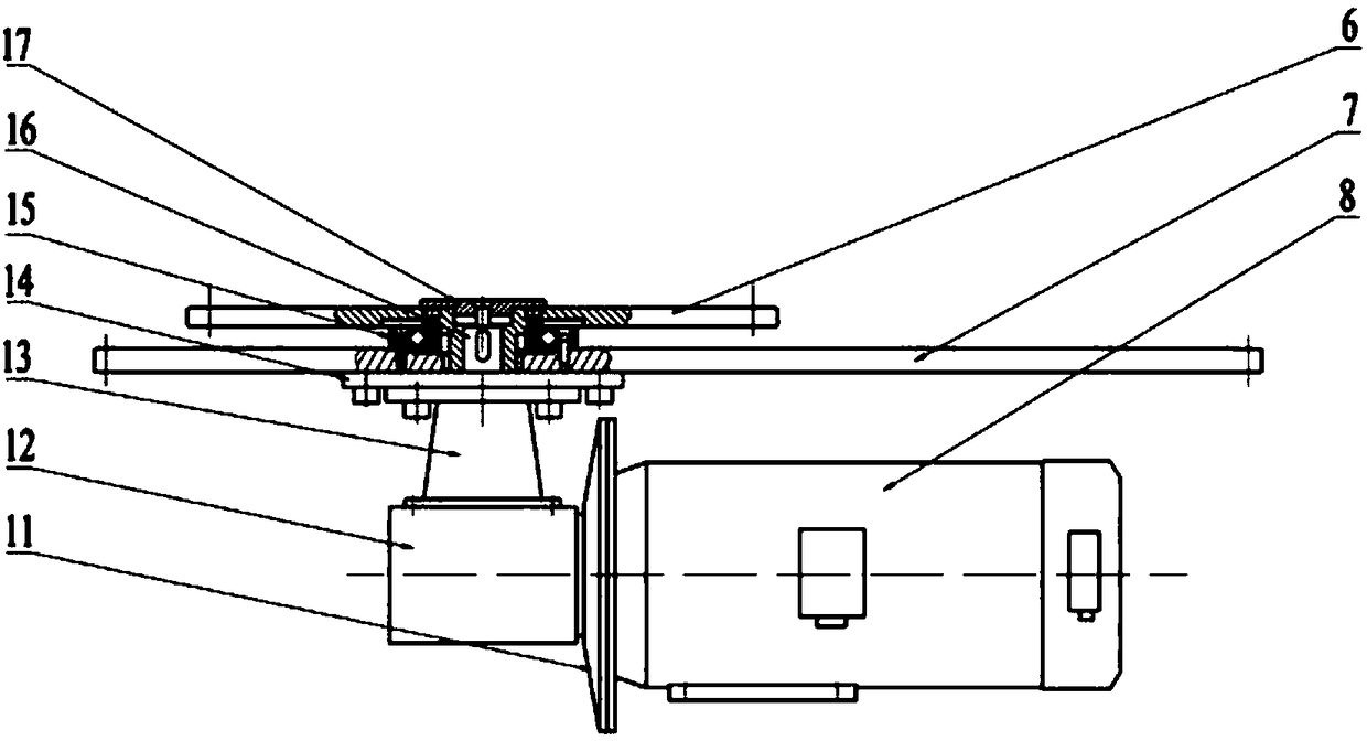
The invention relates to a particle annular Couette shearing flow experiment device, which is characterized by comprising a machine case, a support rod, a cross beam, a shearing chamber, a variable-frequency electric motor and a transmission mechanism, wherein the shearing chamber comprises a bottom disc, an inner round tube and an outer round tube; the inner round tube and the outer round tube are in coaxial arrangement; one end of the inner round tube is coaxially fastened and connected with the bottom disc; a gap is left between the bottom disc and the outer round tube; the other end of theinner round tube is fastened and connected with the cross beam; the support rod is fastened and connected with the cross beam and an upper cover plate arranged on the machine case; the transmission mechanism comprises a rotary disc, a rotary support bearing, a driving shaft and a worm wheel and worm rod speed reducer; the outer round tube is coaxially fastened and connected with the rotary disc;the rotary disc is coaxially fastened and connected with an inner ring of the rotary support bearing; an outer ring of the rotary support bearing is fastened and connected with the upper cover plate of the machine case; one end of the driving shaft is coaxially connected with the rotary disc; the other end of the driving shaft is coaxially connected with an output shaft of the worm wheel and wormrod speed reducer; the variable-frequency electric motor is coaxially connected with an input shaft of the worm wheel and worm rod speed reducer. The experiment device has the advantages that the particle flow characteristics are rich; the experiment precision is high.

Description

technical field [0001] The invention belongs to the technical field of engineering test devices, in particular to a particle annular Couette shear flow test device. Background technique [0002] Particle flow generally refers to the movement state of granular materials similar to flow under the action of external force and internal stress. The phenomenon of particle flow exists widely in nature and industrial processes, such as landslides, debris flows, grain processing and pharmaceutical production. In order to study the particle flow characteristics, a continuous particle flow model needs to be established. The annular Couette particle flow is to confine the particles in two coaxial cylinders, and the particles will flow through the rotation of the inner cylinder and the outer cylinder; the circular Couette particle flow about the rotation of the inner cylinder, due to the inner The diameter of the cylinder is relatively small, resulting in a narrow particle flow area. So...

Claims


Application Information

Patent Timeline
Patent Type & Authority Applications(China)
IPC IPC(8): G01N15/00G01N11/00
CPCG01N11/00G01N15/00G01N2011/008
Inventor 费洪柱李健白剑
Owner NORTHEASTERN UNIV
Learn More