
Torsional vibration damping device

A technology of torsional vibration damping and spring elements, applied in the direction of shock absorbers, transmissions, gear transmissions, etc., to achieve the effect of easy realization and reduced quality

Inactive Publication Date: 2018-10-09
SCHAEFFLER TECH AG & CO KG
View PDF5 Cites 2 Cited by
  • Summary
  • Abstract
  • Description
  • Claims
  • Application Information

AI Technical Summary

Problems solved by technology

Another disadvantage is that the integration of the spring elements increases the quality of rotation

Method used


Image

  • Torsional vibration damping device
  • Torsional vibration damping device
  • Torsional vibration damping device

Examples


Embodiment Construction

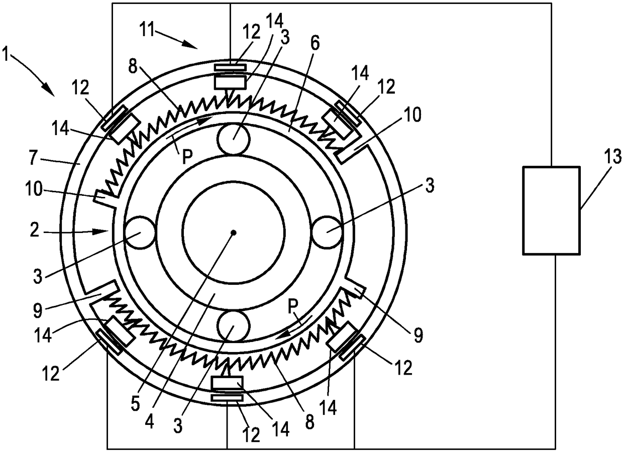
[0024] figure 1 A torsional vibration damping device 1 according to the invention is shown, comprising a planetary gear assembly 2 meshing with a plurality of planetary gears 3 with external toothing, said planetary gears interacting with externally toothed A drive pinion 4 meshes, which is connected to a drive shaft 5 , for example a crankshaft.

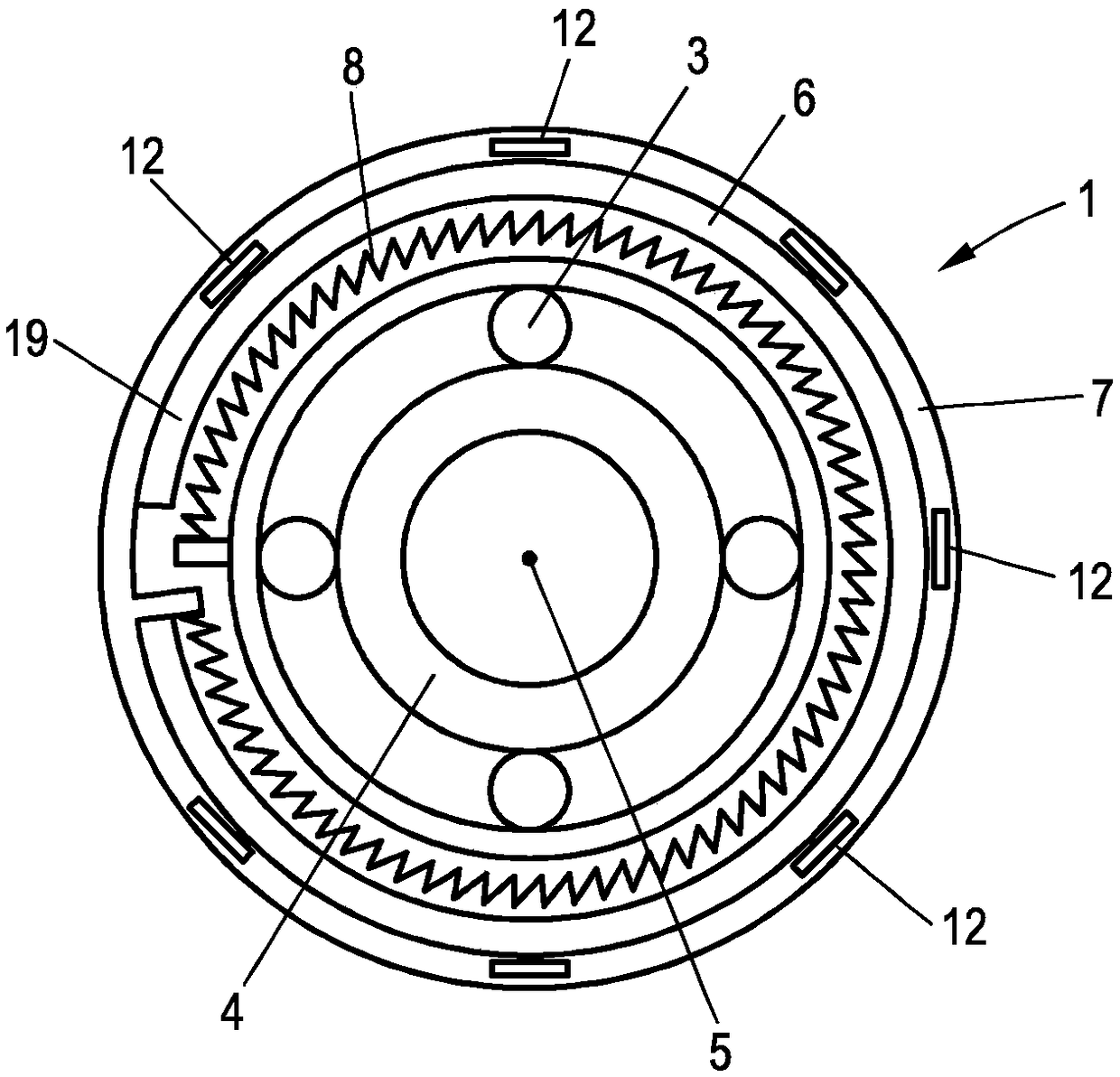
[0025]Furthermore, the planetary gear arrangement 2 includes a hollow gear 6 , the inner toothing of which the planet gears 3 also mesh with. The ring gear 6 itself is rotatable about the axis of rotation of the drive shaft 5 . The ring gear is accommodated in an outer ring component 7 which is, for example, part of the motor housing or the transmission housing or is fastened to such a motor housing or transmission housing. The ring gear 6 is supported relative to the stationary component 7 via two spring elements 8 , here in the form of bent helical springs. For this purpose, in the illustrated embodiment, two radial projections...


PUM


Abstract

A torsional vibration damping device comprises a planetary transmission device assembly which is provided with a plurality of planetary gears which are meshed with a driving pinion which can be drivenby a shaft and at least one spring element for reducing the rotational non-uniformity of the driving pinion. The spring element (8) is arranged outside a hollow wheel (6) which surrounds the planetary gear (3) and rotates around a rotation axis of the driving pinion (4), the planetary gear (3) is meshed with the inner tooth part of the hollow wheel and is supported on the hollow wheel through oneend part and supported on a position fixed bearer (10) by the other end part.

Description

technical field [0001] The invention relates to a torsional vibration damping device comprising a planetary gear assembly with a plurality of planetary gears meshing with a shaft-drivable drive pinion and at least one device for damping rotational inaccuracies of the drive pinion. uniformity of the spring element. Background technique [0002] Such torsional vibration dampers are usually used in connection with internal combustion engines. The drive pinion of the torsional vibration damper is located on the crankshaft of the internal combustion engine. In principle, during operation of the internal combustion engine, rotational irregularities occur at the crankshaft which are disadvantageous and are damped by the torsional vibration damper. For this purpose, a planetary gear assembly is provided on the side of the torsional vibration damper, which is used for power splitting and which is coupled to a spring element. The spring element (eg arc spring) is located in the rot...

Claims


Application Information

Patent Timeline
Patent Type & Authority Applications(China)
IPC IPC(8): F16F15/12F16F15/18
CPCF16F15/12F16F15/18F16F15/1206F16F15/1234F16F15/129F16F2222/06F16H1/28F16F15/121F16F15/133
Inventor T·克劳泽
Owner SCHAEFFLER TECH AG & CO KG
Learn More