Printing apparatus and control method

A technology of printing device and control method, which is applied in the direction of printing device, printing, power transmission device, etc., and can solve problems such as time-consuming, unresolved, and increased product size

Active Publication Date: 2018-10-09
SEIKO EPSON CORP
View PDF7 Cites 0 Cited by
  • Summary
  • Abstract
  • Description
  • Claims
  • Application Information

AI Technical Summary

Problems solved by technology

[0009] However, there is a problem that when the carriage speed is too high, it takes time to accelerate and decelerate. Therefore, when the moving distance of the carriage is short, such as when the printing length is short, it takes time.
[0010] In addition, when shortening the acceleration and deceleration time, there are problems such as the introduction of a high-capacity motor, the increase in the current value, and the cost increase and the increase in product size.
[0011] It should be noted that, in the content described in the above-mentioned patent document 1 and the above-mentioned patent document 2, this problem is not solved.

Method used


Image

  • Printing apparatus and control method
  • Printing apparatus and control method
  • Printing apparatus and control method

Examples


Embodiment Construction

[0034] Hereinafter, embodiments of the present invention will be described with reference to the drawings. However, such embodiment examples do not limit the technical scope of the present invention. It should be noted that in the drawings, the same reference numerals or reference signs are attached to the same or similar parts for description.

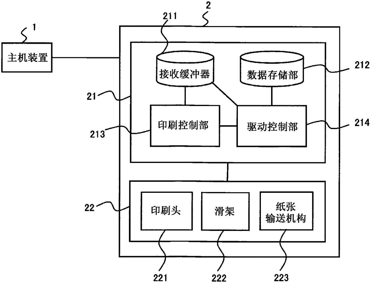
[0035] figure 1 It is a configuration diagram related to an embodiment example of a printing apparatus to which the present invention is applied. figure 1 The illustrated printer 2 is a printing device to which the present invention is applied. In this printer 2 , a carriage 222 on which a print head 221 is mounted moves in the scanning direction SD to print on paper PM. The present printer 2 has a plurality of driving modes with different speeds related to the movement of the carriage 222. During printing, the predicted movement is obtained for each line (one scan) based on the current position of the carriage 222 and the print dat...


PUM


Abstract

The present invention provides a printing apparatus and a control method capable of improving the productivity (throughput) when the moving distance of a carriage such as a short printing length is short, without increasing the cost and the product size. A printing apparatus that scans a printing head and prints on a printing medium has a carriage that mounts the printing head and moves in a scanning direction in a plurality of driving modes having different moving speeds; and a control unit that calculates the predicted moving distance of the carriage during the current scanning process basedon the print data during the scanning process and the position of the carriage, and determines a drive mode during the scanning process based on the predicted moving distance.

Description

technical field [0001] The present invention relates to a printing device and the like capable of improving productivity (throughput) when the moving distance of the carriage is short, such as when the printing length is short, without increasing the cost and the product scale. Background technique [0002] Generally, in a printer in which a carriage on which a printing head is mounted moves in a scanning direction to perform printing, a plurality of drive modes (speed modes) are prepared for the carriage according to printing requirements (print quality, etc.). Furthermore, the speed at which this carriage moves has been increased year by year in order to increase throughput. [0003] Regarding the speed control of the carriage, in the following Patent Document 1, it is described that the distance (L1) from the left end of the movable range of the carriage to the left end of the printing range and the distance (L1) from the right end of the movable range of the carriage to ...

Claims


Application Information

Patent Timeline
IPC IPC(8): B41J19/18B41J25/304B41J29/393
CPCB41J19/18B41J25/304B41J29/393
Inventor 野口昭彦一宫祐太
Owner SEIKO EPSON CORP
Why Eureka
Try Eureka