
Embroidery machine

An embroidery machine and embroidery frame technology, which is applied in the field of embroidery machines, can solve the problems of poor embroidery quality and efficiency, dead angles, and small embroidery area.

Pending Publication Date: 2018-10-02
TAIZHOU YESHI EMBROIDERY MACHINE MFG CO LTD
View PDF0 Cites 9 Cited by
  • Summary
  • Abstract
  • Description
  • Claims
  • Application Information

AI Technical Summary

Problems solved by technology

[0002] Existing embroidery machines generally consist of a workbench and embroidery components, wherein the workbench is used to place embroidery frames with embroidered cloth, and the embroidery components are the main working parts of embroidery, including needles and shuttle boxes for supplying threads to the needles. When working, most embroidery components move horizontally, the embroidery area is small, and there are dead angles, which have a negative impact on the quality and efficiency of embroidery

Method used


Image

  • Embroidery machine
  • Embroidery machine
  • Embroidery machine

Examples


Embodiment Construction

[0033] The purpose of the present invention is to provide an embroidery machine, the structural design of which can make it have a larger embroidery area, avoid embroidery dead angles, and improve embroidery quality and efficiency.

[0034] The following will clearly and completely describe the technical solutions in the embodiments of the present invention with reference to the accompanying drawings in the embodiments of the present invention. Obviously, the described embodiments are only some, not all, embodiments of the present invention. Based on the embodiments of the present invention, all other embodiments obtained by persons of ordinary skill in the art without making creative efforts belong to the protection scope of the present invention.

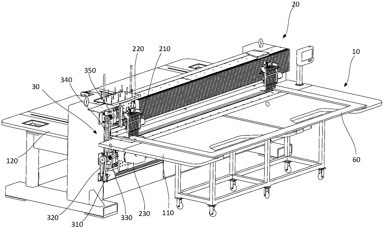
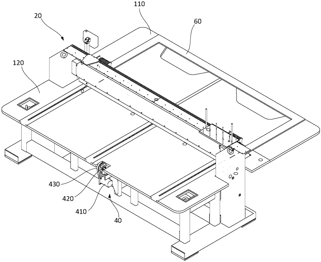
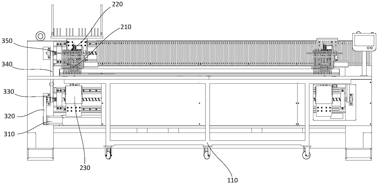
[0035] see Figure 1-Figure 5 , figure 1 The first isometric view of the embroidery machine provided by the embodiment of the present invention, figure 2 The second isometric view of the embroidery machine provided by the embod...


PUM


Abstract

The invention discloses an embroidery machine. The embroidery machine comprises a workbench, an embroidery component, an X-axis moving device and a Y-axis moving device, wherein the workbench is usedfor fixing an embroidery frame; the embroidery component is arranged on the workbench; the X-axis moving device is used for driving the embroidery frame or the embroidery component to move along the X-axis in a reciprocating manner, and the Y-axis moving device is used for driving the embroidery frame or the embroidery component to move along the Y-axis in a reciprocating manner. The embroidery machine has the advantages that by the coordination of the X-axis moving device and the Y-axis moving device, one of the embroidery component and the embroidery frame on the workbench can be allowed tomove along the X-axis and the Y-axis in the horizontal plane relative to the other one of the embroidery component and the embroidery frame on the workbench, the embroidery component can move flexiblyto one optional point in the planar coordinate system formed by the X-axis and the Y-axis, dead angle cannot be formed easily, large embroidery area is achieved, and embroidery quality and efficiencyare increased favorably.

Description

technical field [0001] The invention relates to the technical field of embroidery equipment, in particular to an embroidery machine. Background technique [0002] Existing embroidery machines generally consist of a workbench and embroidery components, wherein the workbench is used to place embroidery frames with embroidered cloth, and the embroidery components are the main working parts of embroidery, including needles and shuttle boxes for supplying threads to the needles. When working, most of the embroidery components move horizontally, the embroidery area is small, and there are dead angles, which have a negative impact on the quality and efficiency of embroidery. [0003] Therefore, how to provide an embroidery machine that has a larger embroidery area, avoids embroidery dead angles, and improves embroidery quality and efficiency has become an important technical problem to be solved urgently by those skilled in the art. Contents of the invention [0004] In view of ...

Claims


Application Information

Patent Timeline
Patent Type & Authority Applications(China)
IPC IPC(8): D05C9/06D05C11/06
CPCD05C9/06D05C11/06
Inventor 叶寒寒
Owner TAIZHOU YESHI EMBROIDERY MACHINE MFG CO LTD
Learn More