
Automatic assembling machine for piston cooling nozzle

A piston cooling nozzle, automatic assembly machine technology, applied in the direction of assembly machines, metal processing, metal processing equipment, etc., can solve the problems of uneven quality, low efficiency, difficulty in automatic assembly of three parts, etc., and achieve high assembly accuracy , fast speed and obvious advantages in market competitiveness

Active Publication Date: 2018-10-02
ZHOUSHAN PUTUO BAOHONG PRECISION MACHINERY
View PDF6 Cites 0 Cited by
  • Summary
  • Abstract
  • Description
  • Claims
  • Application Information

AI Technical Summary

Problems solved by technology

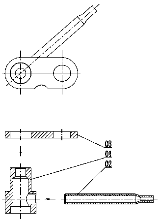
Due to the positional relationship between the valve body 01, the oil pipe 02 and the mounting piece 03, it is difficult to realize the automatic assembly of the three parts
Therefore, at present, the piston cooling nozzles are mostly assembled manually after positioning by tooling, which not only has uneven quality, but also has low efficiency, making it difficult to meet the beat requirements of the production line.

Method used


Image

  • Automatic assembling machine for piston cooling nozzle
  • Automatic assembling machine for piston cooling nozzle
  • Automatic assembling machine for piston cooling nozzle

Examples


Embodiment Construction

[0042] The present invention will be further described below in conjunction with the embodiments and drawings.

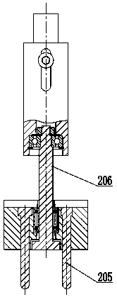
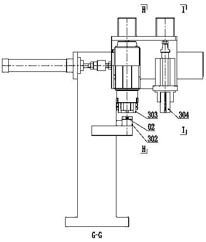
[0043] In the embodiment, such as figure 2 , image 3 , Figure 4 , Figure 5 As shown, an automatic assembly machine for piston cooling nozzles includes: an assembly machine 1, for the pressure pipe assembly of valve body 01 and oil pipe 02, and the pressure plate assembly of valve body 01 and mounting piece 03; valve body positioner 2, It is used to transport valve body 01 and adjust the plug hole on the circumferential wall of valve body 01 to a specified angle; oil pipe positioner 3 is used to transport oil pipe 02 and align the plug end of oil pipe 02 with the plug of valve body 01 The connecting hole is convenient for pressure tube assembly; the installation piece positioner 4 is used to transport the installation piece 03, adjust the front and back of the installation piece 03, the front and back sides, and facilitate the installation of the pressure plate. Aft...


PUM


Abstract

The invention discloses an automatic assembling machine for a piston cooling nozzle. The automatic assembling machine comprises an assembling machine body, a valve body position adjusting machine, a oil pipe position adjusting machine and a mounting piece position adjusting machine; the assembling machine body is used for pipe pressing assembly between the valve body and an oil pipe and plate pressing assembly between the valve body and the a mounting piece; the valve body position adjusting machine is used for conveying the valve body, and adjusting an inserting hole in the circumferential wall of the valve body to a specified angle; the oil pipe position adjusting machine is used for conveying the oil pipe, and enabling the inserting end of the oil pipe to be aligned with the inserting hole of the valve body, and the pipe pressing assembly is facilitated; and the mounting piece position adjusting machine is used for conveying the mounting piece, adjusting the directions and positionsof the front and back faces and the front and rear sides of the mounting piece, and the plate pressing assembly is facilitated. According to the automatic assembling machine, after the valve body position adjusting machine, the oil pipe position adjusting machine and the mounting piece position adjusting machine complete the direction and position adjustment on the valve body, the oil pipe and the mounting piece correspondingly, then, the valve body position adjusting machine, the oil pipe position adjusting machine and the mounting piece position adjusting machine are further transferred tothe assembling machine body to automatically complete pipe pressing assembly and plate pressing assembly, the speed is high, the assembling precision is high, the whole process is free of manual contact, compared with existing manual assembly, the automatic assembling machine has multiple advantages, and the market competitiveness of products is obvious.

Description

Technical field [0001] The invention relates to the field of automatic assembly equipment, in particular to an automatic assembly machine for piston cooling nozzles. Background technique [0002] At present, piston cooling nozzles are commonly used in engines, which spray engine oil to the bottom of the piston after the engine reaches the operating speed to force the piston to cool. The piston cooling nozzle is an important part of the engine's lubrication system, and it has a vital influence on the durability of the piston and even the whole machine. [0003] figure 1 It is a typical piston cooling nozzle, which is assembled by valve body 01, oil pipe 02 and mounting piece 03. The assembly requires that the nozzle has no skew, good cleanliness, and a firm connection. Since the valve body 01, the oil pipe 02 and the mounting piece 03 all have a positional relationship, it is difficult to realize the automatic assembly of the three parts. Therefore, at present, piston cooling nozz...

Claims


Application Information

Patent Timeline
IPC IPC(8): B23P21/00
CPCB23P19/001B23P21/004
Inventor 胡冶红林谦凯林欣久
Owner ZHOUSHAN PUTUO BAOHONG PRECISION MACHINERY
Learn More