
Determining operating mode of electrical machine coupled to internal combustion engine

A state of operation, technology of internal combustion engines, applied in internal combustion engine testing, arrangement of multiple different prime movers of general power plants, machines/engines, etc., to achieve easily achievable results

Inactive Publication Date: 2018-09-28
ROBERT BOSCH GMBH
View PDF5 Cites 3 Cited by
  • Summary
  • Abstract
  • Description
  • Claims
  • Application Information

AI Technical Summary

Problems solved by technology

This method has the disadvantage that the rotational speed of the generator and the internal combustion engine have to be detected separately from each other and the corresponding resulting data have to be transferred via a fast data connection to an external evaluation unit in order to compare them with each other there to identify the belt skidding

Method used


Image

  • Determining operating mode of electrical machine coupled to internal combustion engine
  • Determining operating mode of electrical machine coupled to internal combustion engine
  • Determining operating mode of electrical machine coupled to internal combustion engine

Examples


Embodiment Construction

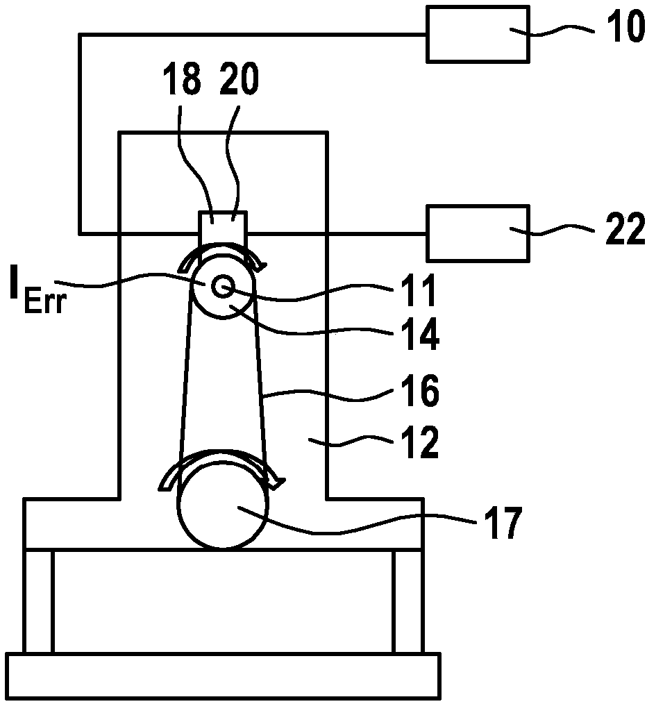
[0042] exist Figure 1a 2 shows a system known from the prior art consisting of a motor vehicle electrical system 10 and an electric machine 14 coupled to an internal combustion engine 12 by means of a flywheel element 11 , wherein the motor vehicle electrical system 10 supplies the electric machine 14 with energy. The electric machine 14 is driven by means of a coupling element 16 , usually a belt drive, wherein the coupling element 16 is arranged on the crankshaft 17 on the part of the internal combustion engine 12 and on a roller provided on the flywheel 11 on the part of the electric machine 14 . In order to regulate the voltage in the onboard electrical system 10 , a computing unit 18 is provided in the form of a regulator 20 , which adjusts the field current I of the electric machine 14 correspondingly depending on the voltage of the onboard electrical system 10 Err .

[0043] By changing the excitation current I Err , the load on the electric machine 14 and thus the de...


PUM


Abstract

The invention relates to a method for determining an operating mode of an electrical machine (114) coupled to an internal combustion engine (112), the method comprising the steps: detecting a plot against time of a phase signal (121) of the electrical machine (114); determining a plot against time of a speed (122) of the electrical machine (114), the speed having oscillating speed oscillations; and determining the operating mode of the electrical machine (114) by comparing the plot against time of the phase signal (121) of the electrical machine (114) and the plot against time of the speed (n). The invention also relates to a corresponding arithmetic unit (118), configured for carrying out the method, and to a corresponding computer programme.

Description

technical field [0001] The invention relates to a method for determining the operating state of an electric machine coupled to an internal combustion engine, as well as to a computing unit, preferably a controller for the electric machine, and to a computer program for carrying out the method. Background technique [0002] To regulate the onboard electrical system voltage in a vehicle, electric machines, in particular externally excited electric machines, can be used. [0003] These electric motors have a regulator which regulates the field current of the electric motor in dependence on the onboard electrical system voltage. The electric machine is coupled to the internal combustion engine via a coupling element, usually a belt drive, wherein the coupling element is acted upon with different torques by the internal combustion engine and by the electric machine (depending on the respective operating state). To protect the belt, the electric motor can have a freewheel element...

Claims


Application Information

Patent Timeline
Patent Type & Authority Applications(China)
IPC IPC(8): G01M13/02B60K6/383F02B67/06G01P3/481G01M15/04G01R31/00H02H7/093
Inventor P·梅林格J·马斯W·费舍
Owner ROBERT BOSCH GMBH
Learn More