
Connector terminal capable of improving opposite insertion retention force

A connector terminal and retention force technology, which is applied in the field of connector terminals to improve the mating retention force, can solve the problems of insufficient connection force, easy loosening and failure of connector terminals and pins, etc.

Pending Publication Date: 2018-09-28
SHENZHEN BUSBAR SCI TECH DEV
View PDF0 Cites 2 Cited by
  • Summary
  • Abstract
  • Description
  • Claims
  • Application Information

AI Technical Summary

Problems solved by technology

[0002] When the existing connector terminals and pins are connected, the connection force is not enough, and the connector terminals and pins are easy to loosen and fail

Method used


Image

  • Connector terminal capable of improving opposite insertion retention force
  • Connector terminal capable of improving opposite insertion retention force
  • Connector terminal capable of improving opposite insertion retention force

Examples


Embodiment Construction

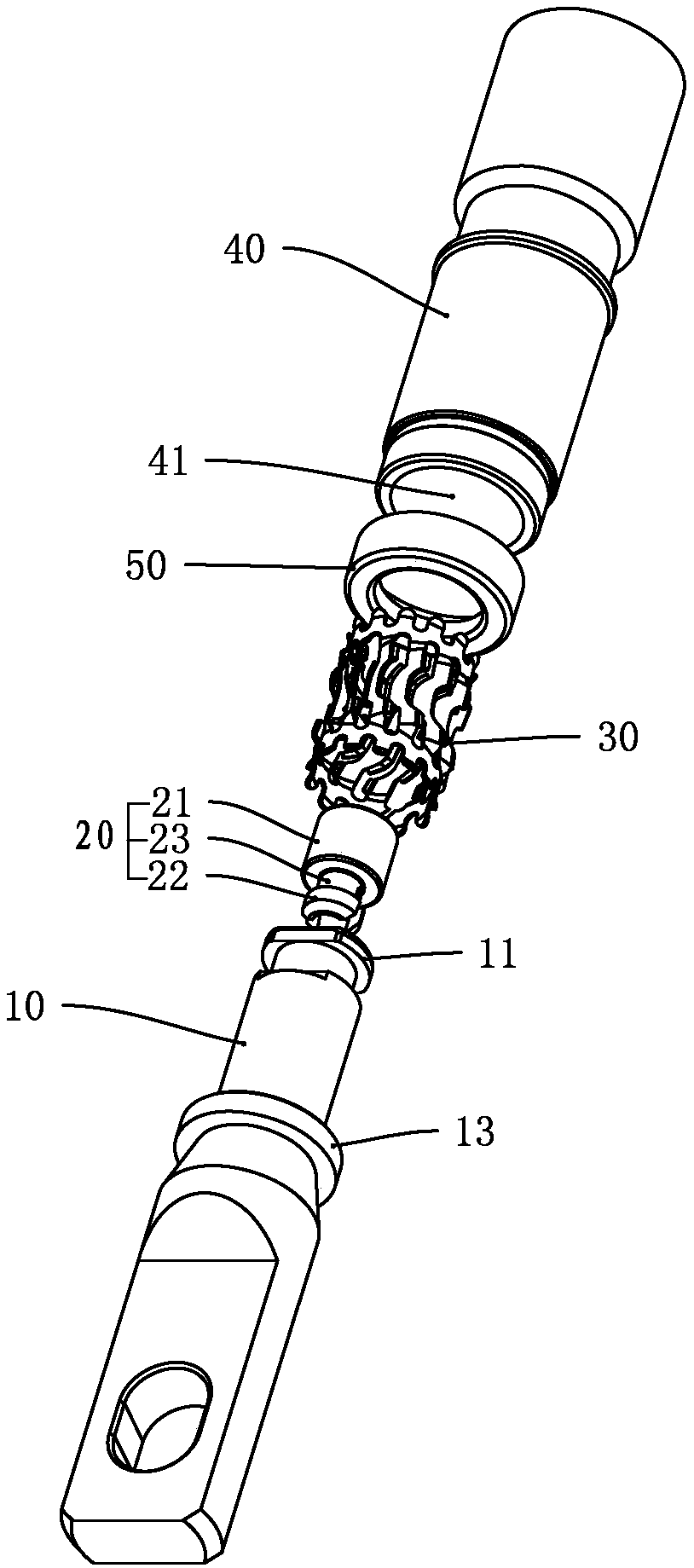
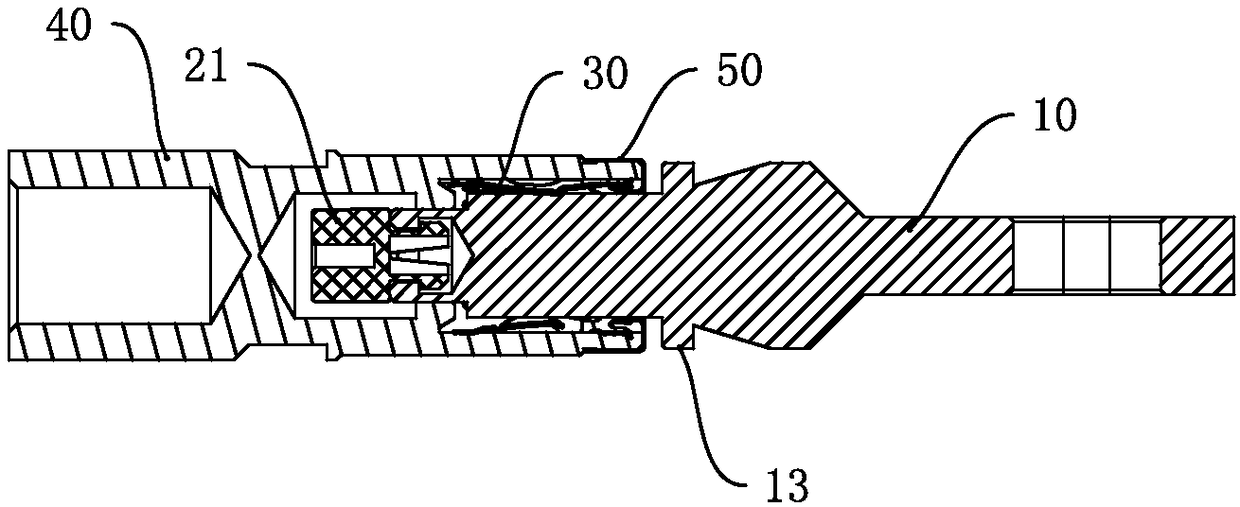
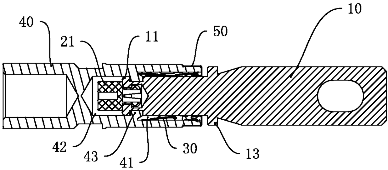
[0018] Such as Figure 1 to Figure 6 As shown, a connector terminal that improves mating retention force includes a pin 10, a protective cap 20, a scale spring 30 and a socket 40. The front end of the socket 40 is concavely provided with a jack 41, and the scale spring 30 is locked. Closely arranged in the socket 41, the socket 41 extends along the axial direction to the rear end of the socket 40 with a first receiving groove 42, and the opposite sides of the inner wall of the first receiving groove 42 are respectively provided with a stopper 43, and the two stoppers 43 form a card interface, the outer wall of the insertion end of the pin 10 is provided with an annular protrusion 11, and the annular protrusion 11 is cut with a gap, and the diameter of the annular protrusion 11 is greater than the distance between the two gear parts 43. The diameter is smaller than the diameter of the first receiving groove 42, the insertion end of the pin 10 is clamped with the protective cap ...


PUM


Abstract

The invention discloses a connector terminal capable of improving opposite insertion retention force. The connector terminal comprises a contact pin, a protection cap, a scale rotational spring and asocket; a jack is formed in the front end plane of the socket in an inward concave manner; the scale rotational spring is tightly clamped in the jack, and the jack extends in the axis direction to theback end of the socket to form a first accommodating groove; baffling parts are arranged on the opposite sides of the inner wall of the first accommodating groove, and a clamping port is formed between the two baffling parts; an annular bump is arranged on the outer wall of the inserting end of the contact pin; a nick is formed in the annular bump in a removing manner; the inserting end of the contact pin is clamped with the protection cap; and after the inserting end of the contact pin is inserted in the scale rotational spring, the contact pin is rotated to enable the annular bump to be tightly clamped with the clamping port. The connector terminal has the advantage that after the inserting end of the contact pin is inserted in the scale rotational spring, the contact pin is rotated toenable the annular bump to be tightly clamped with the clamping port to enable the contact pin and the socket to be in a locking state; and when the contact pin and the socket need to be detached, thecontact pin is rotated for 90 degrees, so that the annular bump and the baffling parts are separated.

Description

technical field [0001] The invention relates to a connector terminal, in particular to a connector terminal which improves the mating holding force. Background technique [0002] When the existing connector terminals are connected to the pins, the connection force is not enough, and the connector terminals and the pins are easy to loosen and fail. Contents of the invention [0003] The purpose of the present invention is to solve the deficiencies of the prior art and provide a soft busbar with flexible connection. [0004] A kind of technical scheme of the present invention: [0005] A connector terminal for improving mating holding force, including a pin, a protective cap, a scale spring and a socket. The front end of the socket faces inwardly and is provided with a socket, and the scale spring is clamped in the socket. The axial direction extends to the rear end of the socket with a first receiving groove, the opposite sides of the inner wall of the first receiving gro...

Claims


Application Information

Patent Timeline
IPC IPC(8): H01R13/187H01R13/213
CPCH01R13/187H01R13/213
Inventor 曾文科黄建芳徐平安林国军
Owner SHENZHEN BUSBAR SCI TECH DEV
Learn More