
Inductive lock

An inductive and lock technology, applied in the field of locks, can solve the problems of difficulty in reducing vehicle costs, time-consuming, and difficult assembly, and achieve the effects of improving control and use convenience, simplifying structure, and facilitating assembly and manufacturing.

Pending Publication Date: 2020-09-11
TOYO JIANN TSANG ELECTRIC CO LTD
View PDF7 Cites 1 Cited by
  • Summary
  • Abstract
  • Description
  • Claims
  • Application Information

AI Technical Summary

Problems solved by technology

[0004] However, in the above-mentioned existing inductive locks, since each button needs to be provided with a corresponding solenoid valve, additional wiring is required to the corresponding position of each solenoid valve, resulting in difficult and time-consuming assembly, which in turn makes it difficult to reduce the cost of the vehicle

Method used


Image

  • Inductive lock
  • Inductive lock
  • Inductive lock

Examples


Embodiment Construction

[0082] In order to make the above-mentioned and other objects, features and advantages of the present invention more obvious and understandable, the preferred embodiments of the present invention are listed below, together with the accompanying drawings, and are described in detail as follows:

[0083] Directionality or similar terms used throughout the invention, such as "front", "rear", "left", "right", "upper (top)", "lower (bottom)", "inner", "outer" , "side", etc., are mainly referring to the directions of the drawings, and each direction or its approximate terms are only used to assist in explaining and understanding various embodiments of the present invention, and are not intended to limit the present invention.

[0084] The elements and components described throughout the present invention use the quantifier "a" or "an" only for convenience and to provide the usual meaning of the scope of the present invention; in the present invention, it should be interpreted as incl...


PUM


Abstract

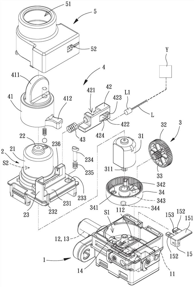
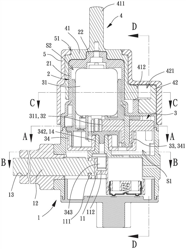
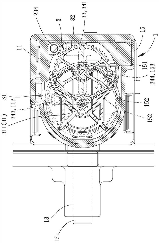
An inductive lock is used for solving the problem that cost of an existing lock can hardly drop. The inductive lock comprises a lock seat, a lock cover, a driving module and an unlocking module, wherein the lock seat is provided with a first sliding piece located in a first containing space, the first sliding piece is provided with a first notch, the lock cover is combined with the upper side of the lock seat and provided with a linkage rod, the linkage rod can be positioned in a penetrating hole vertically movably, the bottom end of the linkage rod extends into the first containing space, thedriving module is located in the lock seat and the lock cover and used for driving the first sliding piece to move, the unlocking module is located outside the lock cover, a rotary knob piece of theunlocking module is provided with an unlocking part, the unlocking part extends into a second notch of a second sliding piece, a concave part of the second sliding piece abuts against the top end of the linkage rod, and when the bottom end of the linkage rod abuts against the first sliding piece, the second sliding piece cannot be driven by the rotary knob piece to slide.

Description

technical field [0001] The invention relates to a lock, in particular to an inductive lock for rolling stock. Background technique [0002] The opening and closing control of the locomotive uses a corresponding key to be inserted into the lock. Through the rotation of the key, it is used to control the opening of the handle, fuel tank, and seat cushion, or to turn on the power supply to start the engine. The key is used for a period of time. After use, its metal profile is easy to wear, and because opening the fuel tank or the compartment cover often needs to be pressed down and rotated, the tightness of the inserted lock is affected, which in turn affects the smooth rotation, and even the vehicle cannot be started. [0003] Therefore, another inductive lock is provided on the market. The way to open the trunk lid or the fuel tank lid is to set a button on the trunk lid or the fuel tank lid respectively. When the vehicle is awakened, the user can press the corresponding butt...

Claims


Application Information

Patent Timeline
Patent Type & Authority Applications(China)
IPC IPC(8): E05B85/00E05B81/04E05B81/34
CPCE05B85/00E05B81/04E05B81/34
Inventor 胡至斌简永盛曾育祺
Owner TOYO JIANN TSANG ELECTRIC CO LTD
Learn More