Laser-heterodyne-interference measuring device and method based on plane mirror reflection

A technology of laser heterodyne interference and measuring device, which is applied to measuring device, adopts optical device, interferometer, etc., can solve the problems of optical thermal drift and complicated optical path structure, and achieves the suppression of optical nonlinear error, simple optical path structure, and difficult optical path structure. Effects of Optical Thermal Drift

Active Publication Date: 2018-09-28
NAT INST OF METROLOGY CHINA
View PDF4 Cites 4 Cited by
  • Summary
  • Abstract
  • Description
  • Claims
  • Application Information

AI Technical Summary

Problems solved by technology

[0006] Aiming at the problems existing in the above-mentioned prior art, the present invention proposes a laser heterodyne interferometry device and method based on plane mirror reflection, which solves the problem of complex optical path structure and easy optical thermal drift in laser heterodyne interferometry, and improves laser performance. Accuracy of heterodyne interferometry

Method used


Image

  • Laser-heterodyne-interference measuring device and method based on plane mirror reflection

Examples


Embodiment 1

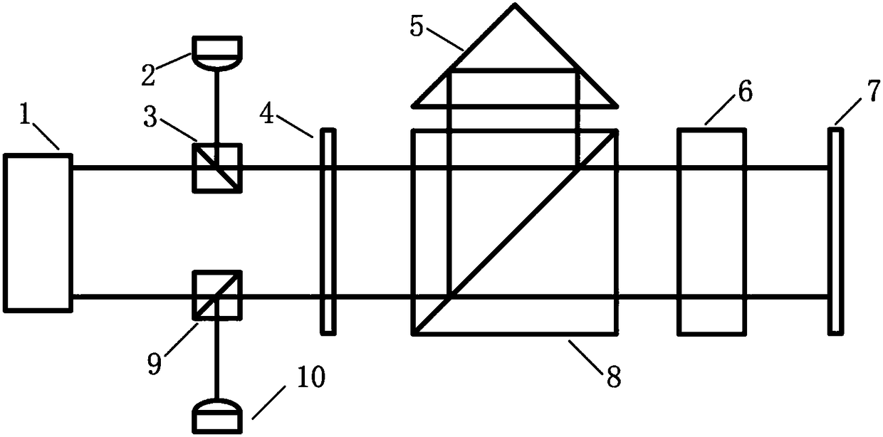
[0041] Example 1: Measuring the displacement of the linear guide stage

[0042] (1) Fix the plane mirror on the stage of the linear guide rail, and move with the linear guide rail;

[0043] (2) set up the interferometric optical path of the present invention, select the right-angle reflector and the optical compensation mirror with the same material and refractive index n, if the optical path of the reference beam in the right-angle reflector is L, then the optical compensation mirror along The thickness measured in the direction of the beam is

[0044] (3) Adjust the direction of the two outgoing lights of the laser so that the direction is parallel to the movement direction of the stage;

[0045] (4) Adjust the angle of the measured plane mirror so that the measuring beam is vertically incident on the measured plane mirror;

[0046] (5) adjust the angle of the third polarization beam splitter and the right-angle mirror, so that the reference beam incident on the photoele...


PUM


Abstract

The invention relates to a laser-heterodyne-interference measuring device and method based on plane mirror reflection. The laser-heterodyne-interference measuring device comprises a dual-frequency laser, a first photoelectric receiver, a second photoelectric receiver, a first polarizing beam splitter, a second polarizing beam splitter, a third polarizing beam splitter, a quarter-wave plate, a corner cube mirror, an optical compensating mirror and a measured plane mirror. According to the method, two beams of different-frequency spatial isolation incident light are utilized for heterodyne-interference measurement, and optical distances between measured light beams and reference light beams are balanced through the optical compensating mirror. In the method, the measured plane mirror reciprocates in the propagation direction of incident light beams. According to the laser-heterodyne-interference measuring device and method, optical non-linear errors and optical thermal drift errors in laser-heterodyne-interference measurement are inhibited, a light path structure is simplified, and the accuracy of laser-heterodyne-interference measurement is increased.

Description

technical field [0001] The invention belongs to the field of laser interferometry, and mainly relates to a laser heterodyne interferometry device and method based on plane mirror reflection. Background technique [0002] The laser heterodyne interferometry method is widely used in ultra-precision geometric parameter measurement, fast ultra-precision positioning, ultra-precision machining and other fields, and its important role in the fields of value traceability and scientific research is becoming increasingly prominent. However, the traditional laser heterodyne interferometry method is difficult to avoid the cross-aliasing between the dual-frequency beams, and then introduces nanometer-scale nonlinear errors. The existence of this error makes it difficult to further improve the measurement accuracy. Although the current heterodyne interferometry method based on the spatial separation of input beams can suppress nonlinear errors, the optical path structure of this method is...

Claims


Application Information

Patent Timeline
Patent Type & Authority Applications(China)
IPC IPC(8): G01B11/02G01B9/02
CPCG01B9/02055G01B11/02G01B9/02007G01B9/02015G01B9/02058G01B2290/45G01B2290/70
Inventor 白洋李正坤鲁云峰张钟华贺青
Owner NAT INST OF METROLOGY CHINA
Why Eureka
Try Eureka