
Electric ignition layered gas injection valve and layered electric ignition pipe column

A technology of electric ignition and gas valve, which is applied in the direction of wellbore/well valve device, production fluid, wellbore/well components, etc., to reduce costs and improve the effect of fire drive

Active Publication Date: 2018-09-28
PETROCHINA CO LTD
View PDF9 Cites 3 Cited by
  • Summary
  • Abstract
  • Description
  • Claims
  • Application Information

AI Technical Summary

Problems solved by technology

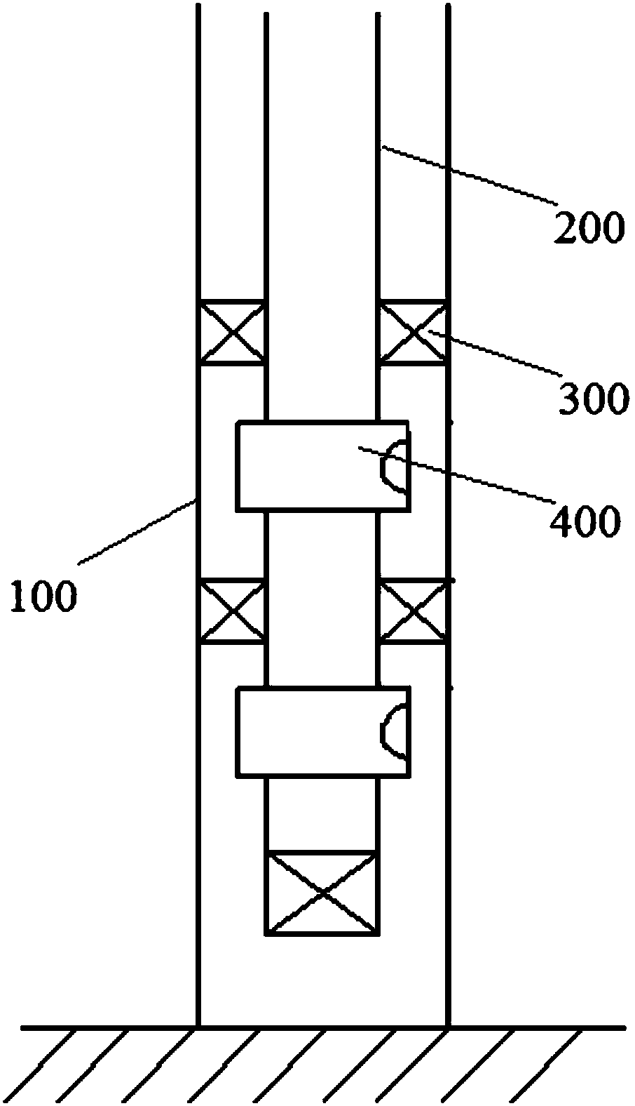
[0005] The purpose of the present invention is to provide an electric ignition layered gas injection valve and a layered electric ignition pipe column to overcome the problems existing in the single layer ignition process in the prior art

Method used


Image

  • Electric ignition layered gas injection valve and layered electric ignition pipe column
  • Electric ignition layered gas injection valve and layered electric ignition pipe column
  • Electric ignition layered gas injection valve and layered electric ignition pipe column

Examples


Embodiment Construction

[0035] In order to enable those skilled in the art to better understand the technical solutions in the present invention, the technical solutions in the embodiments of the present invention will be clearly and completely described below in conjunction with the drawings in the embodiments of the present invention. Obviously, the described The embodiments are only some of the embodiments of the present invention, not all of them. Based on the embodiments of the present invention, all other embodiments obtained by persons of ordinary skill in the art without making creative efforts shall fall within the protection scope of the present invention.

[0036] It should be noted that when an element is referred to as being “disposed on” another element, it may be directly on the other element or there may also be an intervening element. When an element is referred to as being "connected to" another element, it can be directly connected to the other element or intervening elements may a...


PUM


Abstract

The invention discloses an electric ignition layered gas injection valve and a layered electric ignition pipe column. The electric ignition layered gas injection valve comprises an outer pipe extending lengthwise, an inner pipe and a liner pipe. A first gas outlet hole is formed in the outer pipe; the inner pipe is slidably sleeved with the outer pipe, connected with the outer pipe through a shearpin, and a second gas outlet hole is formed in the inner pipe; the inner pipe is positioned on the first position where the second gas outlet hole and the first gas outlet hole communicate by the shear pin; the liner pipe is sleeved with the inner pipe; when the inner pipe is located on the first position, the liner pipe can drive the inner pipe to move to the second position under pushing of anelectric ignition device; and when the inner pipe is located on the second position, the second gas outlet hole does not communicate with the first gas outlet hole, and the liner pipe and the inner pipe are separated. According to the electric ignition layered gas injection valve and the layered electric ignition pipe column, a plurality of oil layers can be ignited in the fireflooding process.

Description

technical field [0001] The invention belongs to the technical field of petroleum downhole tools, and relates to an electric ignition layered gas injection valve and a layered electric ignition pipe string. Background technique [0002] Fire flooding is an important conversion method in the later stage of heavy oil reservoir development. In the process of fire flooding development, there is a large difference in the degree of vertical production of oil reservoirs. The gas absorption of each layer is uneven, and there is a single-layer breakthrough, which makes it difficult to improve the air injection parameters of gas injection wells. It takes effect first, and the low part of the structure takes effect later, and there are problems of uneven effect and sudden phenomenon. The monitoring results of the suction profile show that the overall production degree of fire drive reaches 75%, but there are large differences in the vertical production status. In order to improve the ...

Claims


Application Information

Patent Timeline
Patent Type & Authority Applications(China)
IPC IPC(8): E21B34/12E21B43/16E21B43/243E21B43/14
CPCE21B34/12E21B43/14E21B43/168E21B43/243
Inventor 何传兴魏凯赵树杰田野陈鹏刘佳欣王俊英赵小强刘蔷薇章明张国龙喻波张利军赵辉刘刚
Owner PETROCHINA CO LTD
Learn More