
Unmanned platform vehicle and working method thereof

An unmanned platform and wheel technology, applied in the field of intelligent robots, can solve the problems of troublesome parts replacement, weak protection ability, loss of mobility, etc., and achieve the effect of improving bearing performance, strong mobility, and high passability

Pending Publication Date: 2018-09-28
芜湖正众汽车科技有限公司
View PDF0 Cites 4 Cited by
  • Summary
  • Abstract
  • Description
  • Claims
  • Application Information

AI Technical Summary

Problems solved by technology

[0003] (1) Miniature and light ground unmanned platform vehicles have the advantages of maneuverability and low cost, but limited by the weight of the platform vehicle itself, it is difficult to carry more task loads, its own protection ability is weak, and its speed is low and the range is short , mainly used for combat missions such as reconnaissance, monitoring and bomb disposal
[0004] (2) Heavy and large ground unmanned platform vehicles can carry loads of heavy weight and multiple tasks, and are mainly used for combat tasks such as attack, long-range reconnaissance and mine clearance, but their mobility is relatively poor and the price is high
[0006] However, the frame system of the current unmanned platform vehicle is not assembled and combined, and most of them are welded and load-bearing, and it is troublesome to replace parts; in addition, the suspension system, drive system and frame system are not installed in groups. Once the suspension system and drive system are hit by bombs, missiles or mines, the maneuverability will be completely lost

Method used


Image

  • Unmanned platform vehicle and working method thereof
  • Unmanned platform vehicle and working method thereof
  • Unmanned platform vehicle and working method thereof

Examples


Embodiment Construction

[0039] The specific embodiment of the present invention will be described in further detail by describing the embodiments below with reference to the accompanying drawings, the purpose is to help those skilled in the art to have a more complete, accurate and in-depth understanding of the concept and technical solutions of the present invention, and contribute to its implementation.

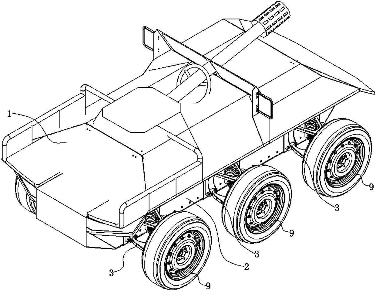
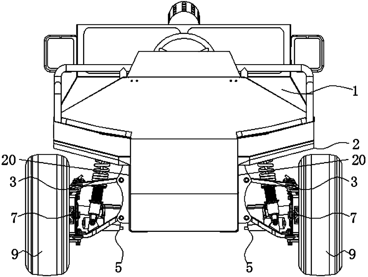
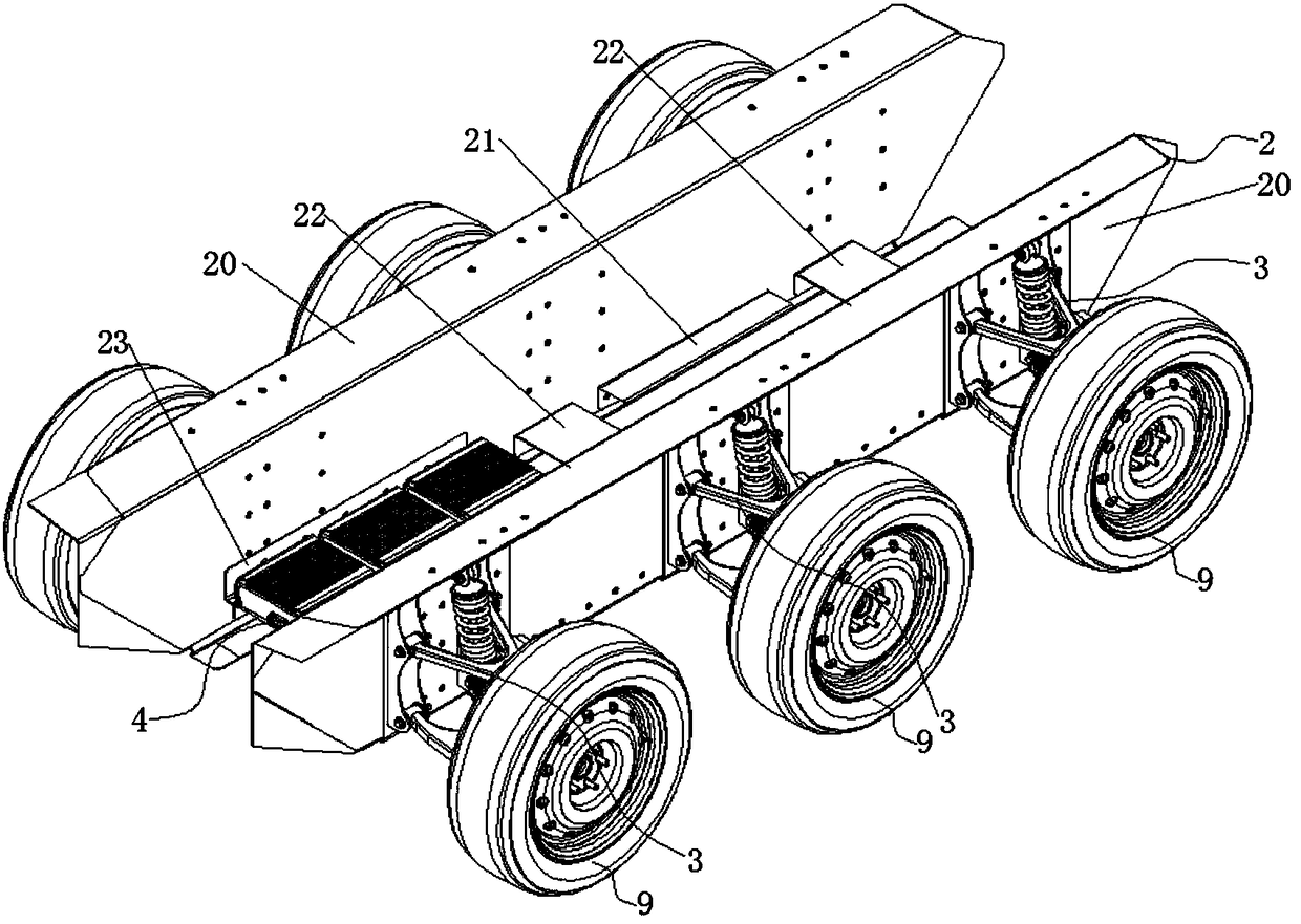
[0040] Such as Figure 1 to Figure 13 As shown, the present invention is an unmanned platform vehicle and its working method, which realizes the modular assembly between the components in the frame system, facilitates the maintenance and replacement of components; realizes the integration of the suspension system and the drive system with the vehicle The modular loading and unloading between rack systems is convenient for mutual replacement and high passability.

[0041] Specifically, if Figure 1 to Figure 13 As shown, it includes a vehicle body 1, a frame system 2, a suspension system 3, a con...


PUM


Abstract

The invention discloses an unmanned platform vehicle and a working method thereof. The unmanned platform vehicle comprises a vehicle body, a vehicle frame system, a suspension system, a controlling system, a steering system, a driving system, a braking system, a battery group and wheels. The vehicle body is connected with the upper end of the vehicle frame system; the vehicle frame system comprises side beam plates, a reinforcing piece, a first connecting piece and a second connecting piece; the suspension system is connected with the lateral faces of the side beam plates, and the suspension system comprises suspension frame installation plates, lower fork arms, upper fork arms, dampers, wheel hub frames and wheel hubs; the driving system comprises wheel hub motors, motor cooling pipelinesand guide wire pipelines; one ends of the steering system are hinged to the outer sides of the suspension frame installation plates, and the other sides of the steering system are hinged to the wheelhub frames; the braking system is connected with the wheel hub frames; the wheels are connected with the wheel hubs; and the battery group is connected with the lower ends of the side beam plates. Modular assembly of all parts in the vehicle frame system is achieved; examination and replacement of the parts are convenient; the modular assembly of the suspension system, the driving system and thevehicle frame system is achieved;and replacement is convenient and passing ability is high.

Description

technical field [0001] The invention belongs to the technical field of intelligent robots. Specifically, the invention relates to an unmanned platform vehicle and a working method thereof. Background technique [0002] The ground unmanned platform vehicle is a robot that can perform specific tasks on the ground. It is a mobile platform with a high degree of integration of mechanization, informationization, and intelligence. Advantages of unmanned design. Ground unmanned platform vehicles can replace humans in high-risk environments to complete a variety of specific tasks that are difficult for humans to complete. It is of great significance to the protection of human life safety and has a wide range of applications. In this regard, there are also various types of unmanned platform vehicles on the market. At present, they are divided into four types: micro, light, heavy, and large according to their weight. Each type has its advantages and disadvantages: [0003] (1) Miniat...

Claims


Application Information

Patent Timeline
IPC IPC(8): B62D61/10
CPCB62D61/10
Inventor 戴兵石正鹏
Owner 芜湖正众汽车科技有限公司
Learn More