Glue spraying device
A technology of spraying glue and conveying mechanism, applied in the direction of spraying device, etc., can solve the problem of low efficiency of manual glue spraying, and achieve the effect of good glue spraying effect, high glue spraying efficiency and health protection.
Active Publication Date: 2018-09-28
陕西华强涂装技术有限公司
View PDF7 Cites 15 Cited by
- Summary
- Abstract
- Description
- Claims
- Application Information
AI Technical Summary
Problems solved by technology
[0004] The object of the present invention is to provide a glue spraying device to solve the problem of low efficiency of manual glue spraying
Method used
View moreImage
Smart ImageViewing Examples

Examples
Embodiment Construction
[0016] The present invention is described in further detail below by specific embodiments:
Login to View More PUM
 Abstract
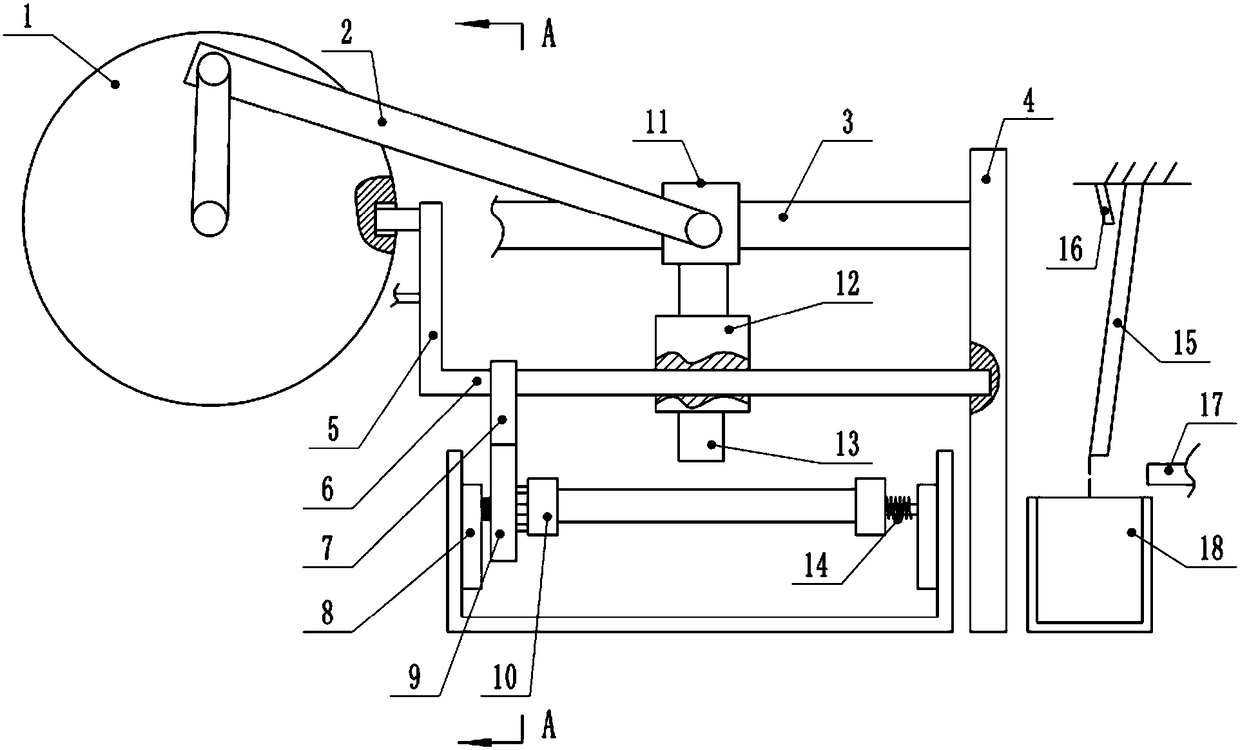
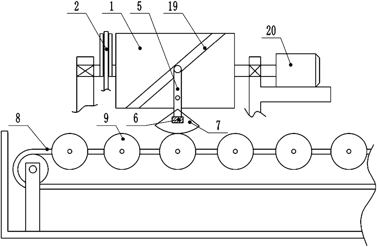
The invention belongs to the technical field of spraying equipment, and particularly relates to a glue spraying device. The glue spraying device comprises a conveying mechanism and a glue spraying part. The conveying mechanism is provided with a plurality of clamping mechanisms; the glue spraying part comprises a reciprocating movement mechanism, a reciprocating swinging mechanism and a glue spraying gun; the reciprocating movement mechanism is a slider-crank mechanism; an installation mechanism is hinged onto a slide block; the reciprocating swinging mechanism comprises a cylinder and a swinging rod; the swinging rod is hinged onto the rack; a curve sliding chute is formed in the curve surface of the cylinder; the upper end of the swinging rod is slidably connected into the curve slidingchute; the cylinder rotates to drive the swinging rod to swing in a reciprocating way through the curve sliding chute; a driving rod is fixed to the lower end of the swinging rod and is parallel to asliding rod; the installation mechanism is slidably connected onto the driving rod; a wabbler mechanism is arranged between the driving rod and the clamping mechanism; and the driving rod swings in areciprocating way so as to drive the clamping mechanism to rotate through the wabbler mechanism. When the glue spraying device provided by the scheme is used for spraying a glue, the glue spraying guncan move front and back in a reciprocating way and swinging left and right in a reciprocating way, and a workpiece can further rotate in a reciprocating way, so that a glue spraying effect is good, and the glue spraying efficiency is high.
Description
technical field [0001] The invention belongs to the technical field of spraying equipment, and particularly relates to a glue spraying device. Background technique [0002] In recent years, the development momentum of my country's automobile industry has been strong. China has become the third country after the United States and Japan with an annual output of over 10 million vehicles, and has entered the ranks of the largest countries with 10 million vehicles. In order to meet the rapid development requirements of the automobile industry, the structure, quality and quantity of the parts produced are increasingly required for the auto parts manufacturers who play a decisive role in the production speed and quality of the automobile. [0003] With the continuous improvement of people's economic income and the rapid development of the automobile industry, automobiles have increasingly entered ordinary households and become a new growth point for residents' consumption. Because ...
Claims
Login to View More Application Information
Patent Timeline
 Patent Type & Authority Applications(China)
IPC IPC(8): B05B13/04B05B13/02B05B14/00
CPCB05B13/0221B05B13/041B05B14/00
Inventor 熊强
Owner 陕西华强涂装技术有限公司
Features
- R&D
- Intellectual Property
- Life Sciences
- Materials
- Tech Scout
- Unparalleled Data Quality
- Higher Quality Content
- 60% Fewer Hallucinations
Learn More Browse by: Latest US Patents, China's latest patents, Technical Efficacy Thesaurus, Application Domain, Technology Topic, Popular Technical Reports.
© 2025 PatSnap. All rights reserved.Legal|Privacy policy|Modern Slavery Act Transparency Statement|Sitemap|About US| Contact US: help@patsnap.com