
Air energy turbine type hot-air engine

A hot air engine and air energy technology, which is applied to combined engines, engine components, machines/engines, etc., can solve the problems of low effective utilization rate, exhaust gas emission, and cumbersome machines, so as to achieve improved effective utilization rate, simple overall structure, Effects of controlling power output

Pending Publication Date: 2018-09-25
王闯业
View PDF5 Cites 0 Cited by
  • Summary
  • Abstract
  • Description
  • Claims
  • Application Information

AI Technical Summary

Problems solved by technology

However, the power adjustment control and power output mechanism of the existing heat engine are relatively complicated, the machine is relatively heavy, and the effective utilization rate is low, which affects the popularization and application of the heat engine
[0003] The engine is one of the main equipment that provides power, including heat turbines, water turbines, gasoline engines, internal combustion engines, and external combustion engines. These engines need to provide considerable energy to do work, but they all consume considerable energy from outside. Especially in the use of internal combustion engines, there are also characteristics of exhaust gas and environmental pollution.

Method used


Image

  • Air energy turbine type hot-air engine
  • Air energy turbine type hot-air engine
  • Air energy turbine type hot-air engine

Examples


Embodiment Construction

[0028] Specific embodiments of the present invention will be described in detail below in conjunction with the accompanying drawings.

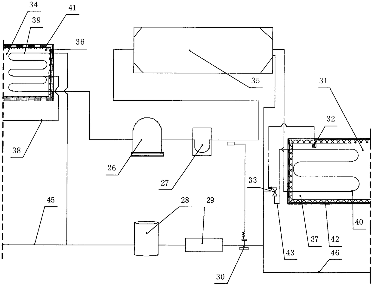
[0029] The novel air energy heater of the present invention is mainly composed of six parts: an air energy heating mechanism, a thermal chamber 34, a cooling chamber 37, an airflow mechanism, an airflow return mechanism and a turbine driving mechanism. The concrete structure of force chamber 37 is as figure 1 As shown, the air energy heating device is mainly composed of a compressor 26, a gas-liquid separator 27, an evaporator 35, an expansion valve 30, a filter 29, and a liquid storage tank 28 connected in series through pipelines. The above-mentioned compressor 26, gas-liquid separation The working principle of the device 27, the evaporator 35, the expansion valve 30, the filter 29 and the liquid storage tank 28 is the same as that of the existing air energy water heater, and will not be repeated here.

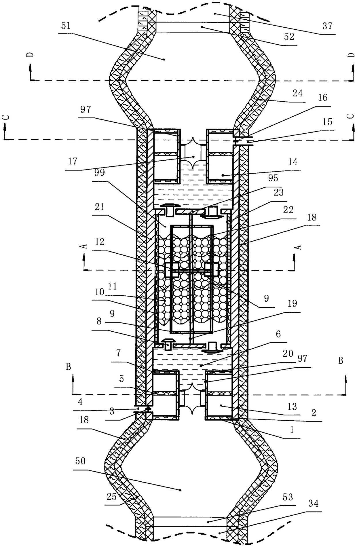
[0030] Thermal chamber 34 comprises ...


PUM


Abstract

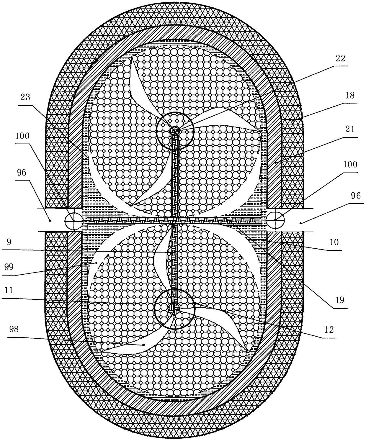
The invention discloses an air energy turbine type hot-air engine. A barrel is arranged in the middle of two cylinders, and a hot air chamber close to a hot cavity and a cold air chamber close to a cold cavity are respectively installed at two ends of an air flow passage. The hot air chamber and the cold air chamber are respectively provided with a hot medium nozzle and a cold medium nozzle, and amedium recovery chamber is arranged on a central air flow passage. The medium recovery chamber is provided with a rotor wind wheel and filled with a filter element, and a medium return port is formedin the wall of an air selection chamber. Return air flow passages leading to a cold end turbine cavity and a hot end turbine cavity are arranged on the cylinder walls of the hot cavity and the cold cavity, and the cold end turbine cavity and the hot end turbine cavity are separated by a piston in the turbine cavity center. The power output of the turbine engine can be controlled and adjusted by injecting the hot medium and the cold medium into the cylinder, the effective utilization rate is improved, and the hot-air engine has the advantages of being simple in structure and convenient to use.

Description

technical field [0001] The invention relates to an air energy turbine heat engine, which relates to the field of heat engines. Background technique [0002] The heat engine is an external combustion, closed cycle reciprocating piston heat engine heat engine. It can use various liquid, gaseous or solid energy sources, and has good torque characteristics in a wide speed range, so it is very suitable for vehicle use. However, the power adjustment control and power output mechanism of the existing heat engine are relatively complicated, the machine is relatively heavy, and the effective utilization rate is low, which affects the popularization and application of the heat engine. [0003] The engine is one of the main equipment that provides power, including heat turbines, water turbines, gasoline engines, internal combustion engines, and external combustion engines. These engines need to provide considerable energy to do work, but they all consume considerable energy from outsi...

Claims


Application Information

Patent Timeline
Patent Type & Authority Applications(China)
IPC IPC(8): F01D15/10F01D13/02F01D17/10F01D17/12F01D25/10F01D25/12F01D25/14
CPCF03G2007/007F01D13/003F01D13/02F01D15/10F01D17/10F01D17/12F01D25/10F01D25/12F01D25/145F03G7/04
Inventor 王闯业
Owner 王闯业
Learn More