Automatically controlled electronic device key performance detecting device

A technology of automatic control and electronic equipment, which is applied in branch office equipment, telephone communication, electrical components, etc., can solve the problems of reducing work efficiency, confusion of mobile phones, and poor accuracy of detection data, and achieves a wide range of use, improved recognition, and detection effects Good results

Active Publication Date: 2018-09-21
锐青科技(重庆)有限公司
View PDF5 Cites 2 Cited by
  • Summary
  • Abstract
  • Description
  • Claims
  • Application Information

AI Technical Summary

Problems solved by technology

[0006] The object of the present invention is to provide a kind of automatically controlled electronic equipment key performance detection device, to solve the existing mobile phone key performance detection device proposed in the above background technology with simple structure design and poor accuracy of detection data; There is a mobile phone storage area, and the mobile phones cannot be placed in partitions, which is prone to confusion between checked mobile phones and unchecked mobile phones, which affects the inspection data; the existing equipment is suitable for a small range of mobile phones, and is aimed at different mobile phone buttons. It is necessary to replace the detection mold at the position, which is easy to waste working time and reduce work efficiency; the existing one cannot record the whole process of mobile phone detection, and cannot further improve the mobile phone through the reflection of the mobile phone screen; so for the existing equipment Insufficient, need to further improve the existing equipment, in order to make the detection data more accurate and more effective

Method used


Image

  • Automatically controlled electronic device key performance detecting device
  • Automatically controlled electronic device key performance detecting device
  • Automatically controlled electronic device key performance detecting device

Examples


Embodiment

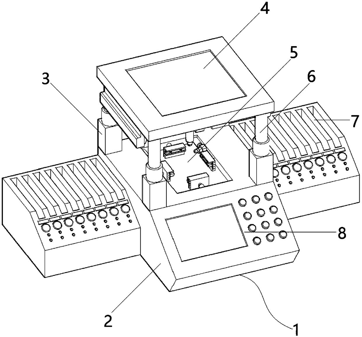
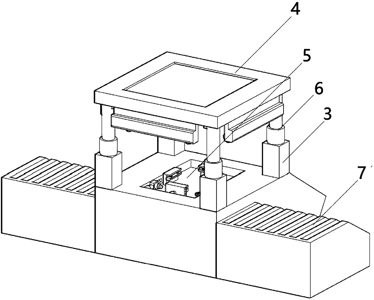
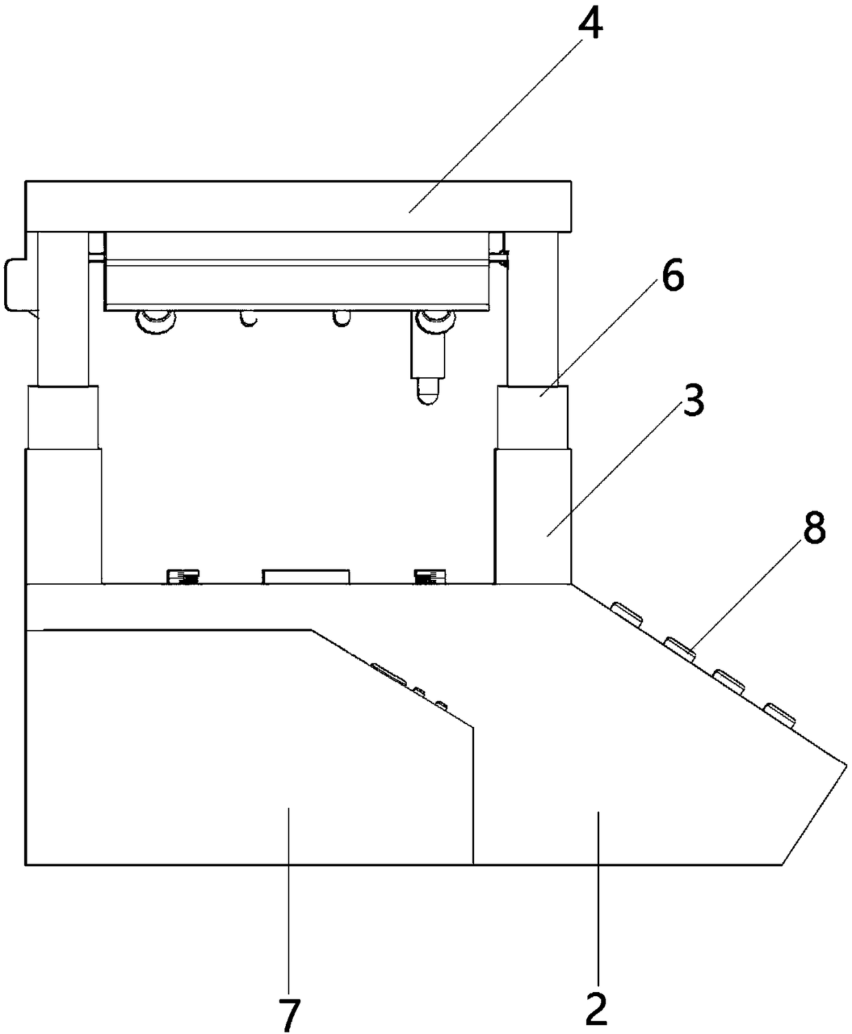
[0044] as attached figure 1 to attach Figure 12 Shown:

[0045] The present invention provides an orthopedic splint with drug penetration, comprising a device body 1, a device base 2, a support column 3, a device top cover 4, a transparent glass cover 401, an upper button test rod 402, and a driving screw shaft device 403 , recording fixed plate 404, illuminating lamp 404a, high-definition camera 404b, mobile phone limit slot 5, mobile phone left and right button test rod 501, mobile limit block 501a, telescopic detection button 501b, mobile adjustment cylinder 501c, mobile phone limit block 502, clamp Tightening spring 502a, limit block adjustment cylinder 502b, measuring scale 502c, clamping block 502d, lifting cylinder 6, mobile phone storage slot 7, mobile phone slot 701, serial number display screen 702, indicator light 703, light control button 704 and control panel 8. The bottom side of the device body 1 is provided with a device base 2; the two sides of the device b...


PUM


Abstract

The invention provides an automatically controlled electronic device key performance detecting device comprising a device base, a device top cover and a mobile phone limiting groove, wherein the device base is arranged on the bottom side of the device main body; mobile phone storage grooves are symmetrically formed in both sides of the device base; a control panel is arranged on a front side inclined plane of the device base; supporting columns are symmetrically arranged on the four corners of the upper end of the device base; lifting cylinders are arranged at the top ends of the supporting columns; the mobile phone limiting groove is formed in the middle position of the top side of the device base; and mobile phone left and right key test rods are symmetrically arranged on both sides of one end of an inner side wall of the mobile phone limiting groove. According to the automatically controlled electronic device key performance detecting device, two left and right mobile phone storagegrooves are formed, and the two mobile phone storage grooves are respectively set as a to-be-detected area and a detected area, which is conducive to separately placing the detected mobile phones so as to prevent confusion from affecting the accuracy of detection.

Description

technical field [0001] The invention relates to the technical field of mobile phone testing equipment, in particular to an automatic control electronic equipment key performance testing device. Background technique [0002] With the progress of society, mobile phones, as one of the indispensable communication tools in people's lives, are being used more and more widely. As one of the essential components on mobile phones, mobile phone buttons play a vital role. Now All mobile phones that leave the factory must test the keys of the mobile phone, thereby preventing many unqualified products from entering the market, and effectively preventing inconvenience to purchasers. [0003] The invention with the existing patent No. 201710864714.0 relates to a method for testing the keys of a mobile phone, including: placing the mobile phone to be tested in a groove on the workbench of the mobile phone to be tested, and the depth of the groove is 0.5 times the thickness of the mobile pho...

Claims


Application Information

Patent Timeline
IPC IPC(8): H04M1/24
CPCH04M1/24
Inventor 韦宜
Owner 锐青科技(重庆)有限公司
Why Eureka
Try Eureka