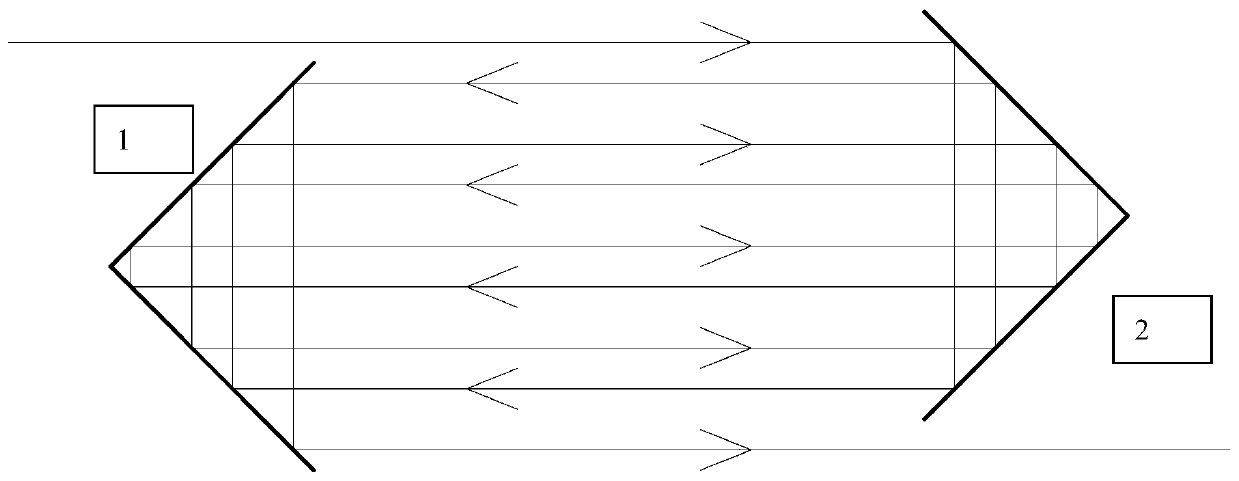
A Four Right Angle Reflectors Extending Optical Length System
A right-angle mirror and optical path-enhancing technology, applied in the optical field, can solve the problems such as the inability to greatly improve the detection accuracy, the limited effect of the compressed space, and the inability to achieve miniaturization, so as to promote the improvement of the accuracy of the detection equipment and improve the efficiency of the equipment. , the effect of promoting the development of miniaturization
- Summary
- Abstract
- Description
- Claims
- Application Information
AI Technical Summary
Problems solved by technology
Method used
Image
Examples
Embodiment 1
[0035] figure 1 It is a schematic diagram of the three-dimensional structure of the optical length increasing system of four right-angle mirrors according to an embodiment of the present invention.
[0036] As shown in the figure, right-angle mirror 1 and right-angle mirror 2 form an inner right-angle mirror group, and right-angle mirror 3 and right-angle mirror 4 form an outer right-angle mirror group. Right-angle reflector 1 and right-angle reflector 2 have a certain offset in the left and right directions, the inner right-angle reflector 2 on the right side of the figure is offset inward from the paper, and the right-angle reflector 1 on the left in the figure is offset outward from the paper surface, so Although the right-angle reflector 1 and the right-angle reflector 2 are opposite to each other, they are not completely opposite. There is a gap at the edge of the right-angle reflector 1. When the light exits from the edge of the right-angle reflector 2, the right-angle r...
Embodiment 2
[0042] figure 2 It is a schematic diagram of the three-dimensional structure of the optical length-enhancing system of four right-angle mirrors according to another embodiment of the present invention.
[0043] Such as figure 2 As shown, this embodiment still uses four right-angle mirrors, but the arrangement is slightly different from that of Embodiment 1.
[0044] The right-angle vertex of one right-angle reflector in the inner right-angle reflector group leaves a light-through slit, and one of the right-angle reflectors 3 of the outer right-angle reflector group is placed on the right-angle reflector 1 with the light-through slit. The back of the reflective surface, and the reflective surface is facing the light-passing slit, so that when the reflected light incident from the slit to the outer right-angle reflector 3 is reflected back to the slit from the outer right-angle reflector 3, the reflected light is reflected along the inner right angle. There is a certain spat...
Embodiment 3
[0049] Figure 4 Another structure of the present invention is the structure of the embodiment. In this four right-angle reflector system, the arrangement of the inner right-angle reflector group and the outer right-angle reflector group is the same as that of embodiment 1, but in this embodiment, Two confocal focusing optics are added between the two right-angle mirrors in the inner right-angle mirror group to form a confocal optical set. The optical axis of the focusing optical set is parallel to the incident light. The focusing optical set makes the The parallel light reflected by one of the right-angle mirrors in the mirror group is focused by one of the optical trains to the focal point, and then becomes parallel light by the other focusing optical train, and then transmitted to the other right-angle mirror of the inner right-angle mirror group . In this way, multiple focusing of the parallel light on the focal point of the confocal optical system can be realized, thereb...
PUM
 Abstract
Description
Claims
Application Information
 - R&D
- Intellectual Property
- Life Sciences
- Materials
- Tech Scout
- Unparalleled Data Quality
- Higher Quality Content
- 60% Fewer Hallucinations
Browse by: Latest US Patents, China's latest patents, Technical Efficacy Thesaurus, Application Domain, Technology Topic, Popular Technical Reports.
© 2025 PatSnap. All rights reserved.Legal|Privacy policy|Modern Slavery Act Transparency Statement|Sitemap|About US| Contact US: help@patsnap.com


