
Precision mirror frame based on a flexible hinge

A reflective mirror frame and flexible hinge technology, which is applied in installation, optics, instruments, etc., can solve the problems that the light path is easily affected by external factors such as vibration and temperature, the technical requirements of optical mechanical engineers are high, and the adjustment accuracy of the mirror frame is difficult to grasp. , to achieve the effects of wide application space, reduced adjustment difficulty, and easy operation

Pending Publication Date: 2018-09-21
NAT UNIV OF DEFENSE TECH
View PDF0 Cites 10 Cited by
  • Summary
  • Abstract
  • Description
  • Claims
  • Application Information

AI Technical Summary

Problems solved by technology

The reflector frame used in scientific experiments usually uses fine-tooth screws and springs to adjust the angle of the reflector surface. The adjustment accuracy is high and repeated adjustments can be realized, but the stability is poor. The adjusted optical path is easily affected by vibration. Influenced by external factors such as temperature, it is not suitable for use in high-vibration platforms such as vehicles
In optical equipment or engineering tasks, fixed mirror frames are usually used. After the optical path is adjusted, screw fastening or glue curing is used to fix it to prevent external vibrations from affecting the optical path. However, the adjustment accuracy of this mirror frame is difficult to grasp. Optomechanical engineers have high technical requirements

Method used


Image

  • Precision mirror frame based on a flexible hinge
  • Precision mirror frame based on a flexible hinge
  • Precision mirror frame based on a flexible hinge

Examples


Embodiment 1

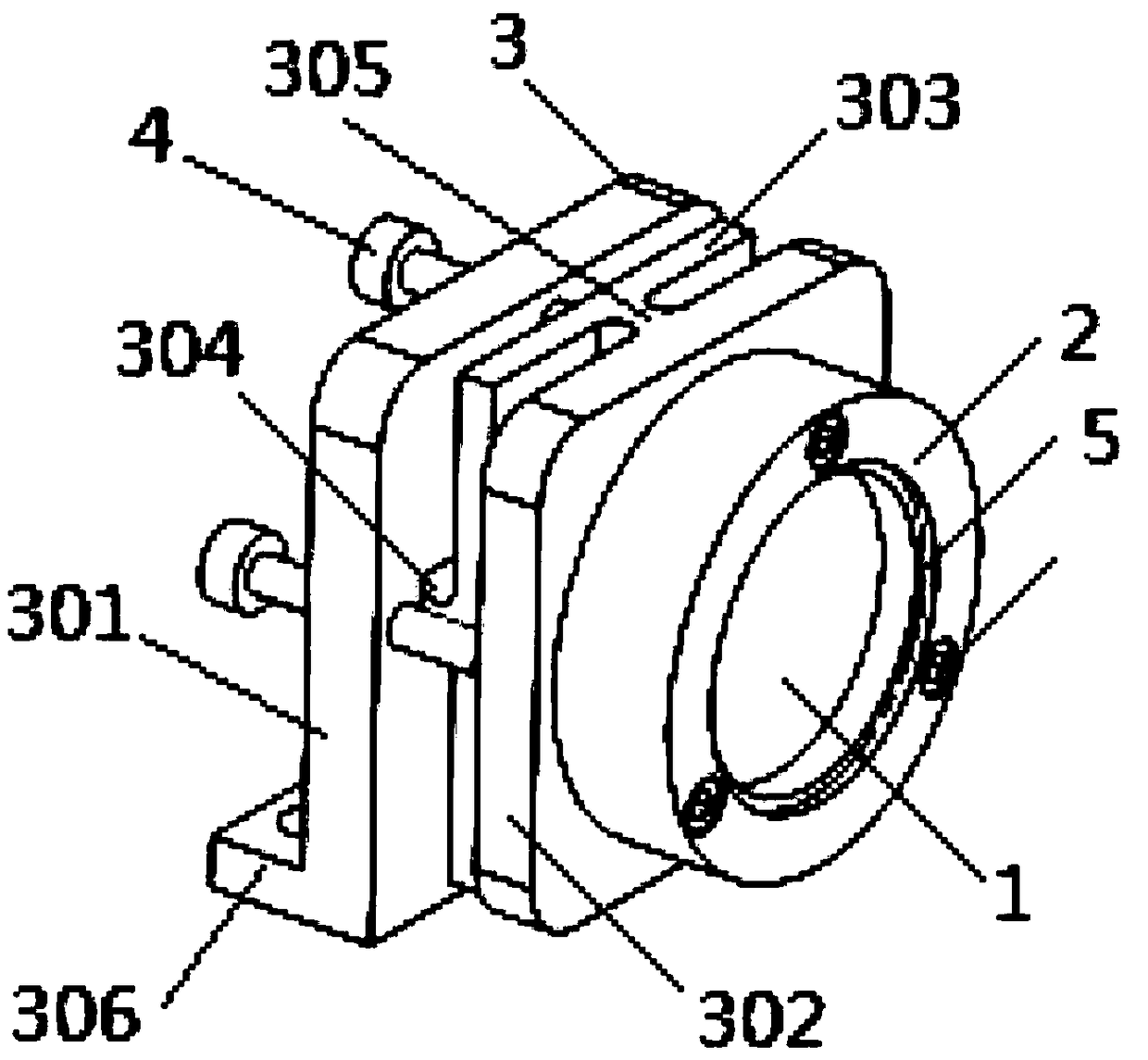
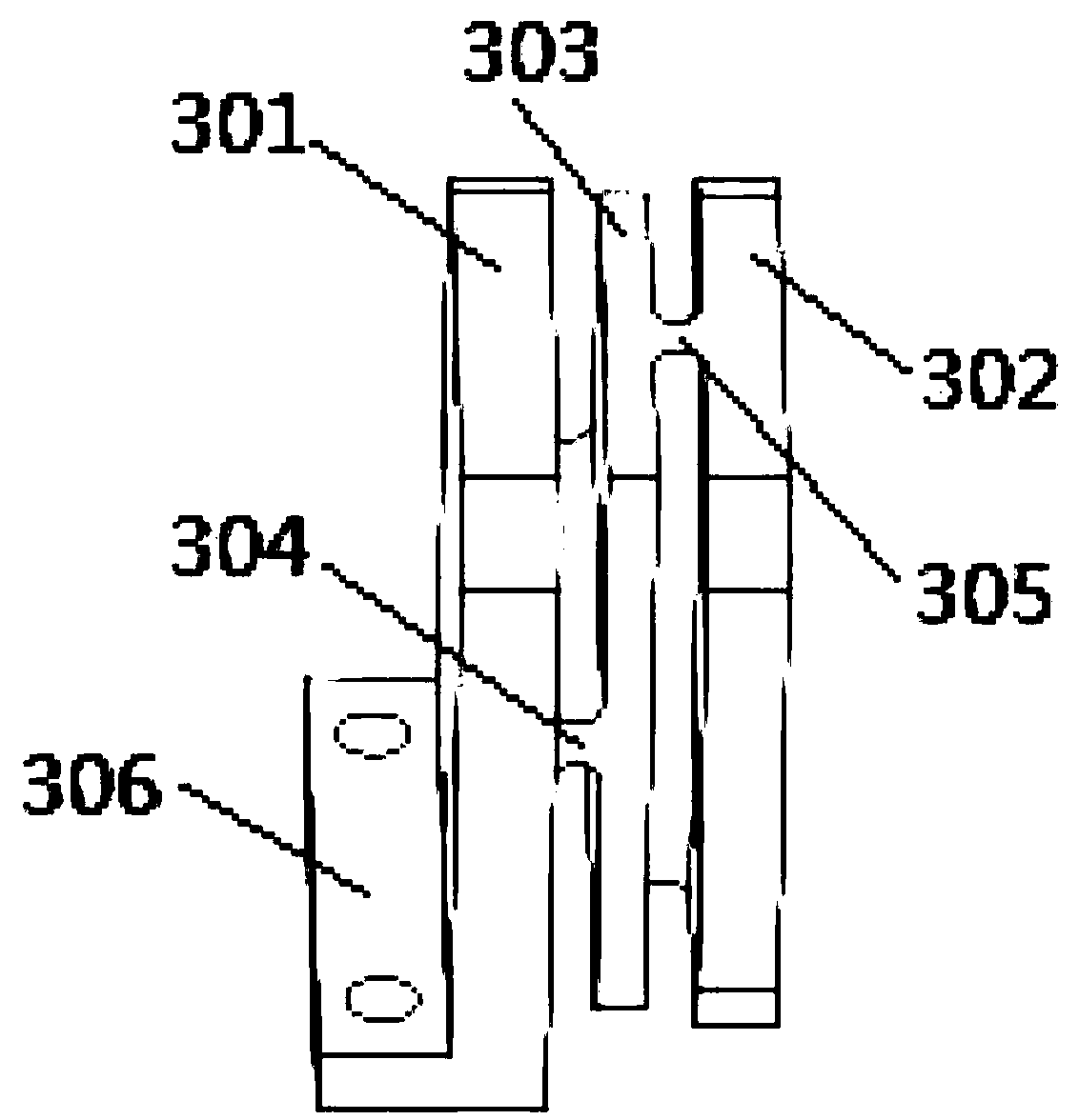
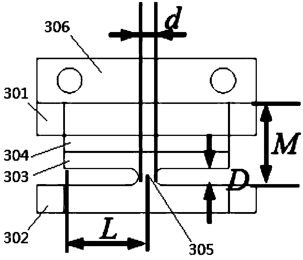
[0025] as attached Figure 1-5 As shown, a precision mirror frame based on a flexible hinge includes a mirror 1, a mirror holder 2 for installing the mirror 1, a base 3 for supporting the mirror holder 2, and a mirror 1 for adjusting the angle The adjustment unit 4, the base 3 includes a fixed plate 301, an adjustable plate 302 and a connecting plate 303 arranged between the fixed plate 301 and the adjusting plate 302, the fixed plate 301 and the connecting plate 303 are connected by a first hinge 304, and the adjustment The plate 302 and the connecting plate 303 are connected by a second hinge 305. The fixing plate 301 is provided with an adjusting unit 4 for adjusting the angle between the fixing plate 301 and the adjusting plate 302. The adjusting plate 302 is fixedly installed on one side away from the connecting plate 303. There is a mirror holder 2 on which a reflector 1 is installed; the thickness d of the first hinge 304 and the second hinge 305 ranges from 1 to 10 mm,...


PUM


Abstract

The present invention relates to a precision mirror frame based on a flexible hinge, and belongs to the technical field of optical components. The mirror frame includes a mirror group for mounting a mirror, a base for supporting the mirror group, and an adjusting unit for adjusting the angle of the mirror group. The base includes a fixing plate and a connecting plate disposed between the fixing plate and the mirror group, and the fixing plate and the connecting plate are hinged by the first hinge. The connecting plate and the mirror group are hinged by a second hinge, and the first hinge and the second hinge define a different rotation direction. The fixing plate is provided with an adjusting unit, and the adjusting unit is an adjusting bolt. The mirror set includes an adjustment plate, amirror holder, and a mirror press ring. The mirror frame has the advantages of simple structure, convenient installation, and the functions of the mirror adjusting unit and the fixed frame of the existing fine screw with the spring, which ensures the precision and stability of the mirror adjustment, and reduces the adjustment difficulty of the mirror frame, with wide application space.

Description

technical field [0001] The invention belongs to the technical field of optical components, in particular to a flexible hinge-based precision mirror frame. Background technique [0002] Mirror holders are mainly used to change the propagation direction of light beams, and are widely used in optical-related scientific experiments, instruments and engineering projects. The reflector frame used in scientific experiments usually uses fine-tooth screws and springs to adjust the angle of the reflector surface. The adjustment accuracy is high and repeated adjustments can be realized, but the stability is poor. The adjusted optical path is easily affected by vibration. Influenced by external factors such as temperature, it is not suitable for use in high-vibration platforms such as vehicles. In optical equipment or engineering tasks, fixed mirror frames are usually used. After the optical path is adjusted, screw fastening or glue curing is used to fix it to prevent external vibratio...

Claims


Application Information

Patent Timeline
IPC IPC(8): G02B7/182
CPCG02B7/1821
Inventor 马阎星支冬杨家忠粟荣涛马鹏飞吴坚周朴
Owner NAT UNIV OF DEFENSE TECH
Learn More