Steel tube feeding device

A technology of feeding device and receiving device, which is applied in the direction of transportation and packaging, conveyors, conveyor objects, etc., can solve problems such as low work efficiency, potential safety hazards, and troublesome steel pipe operation, so as to reduce labor intensity, avoid potential safety hazards, The effect of improving work efficiency

Inactive Publication Date: 2018-09-21
芜湖良匠机械制造有限公司
View PDF0 Cites 17 Cited by
  • Summary
  • Abstract
  • Description
  • Claims
  • Application Information

AI Technical Summary

Problems solved by technology

[0002] Steel pipes are widely used in today's society, such as petrochemical industry and heat exchangers, etc. In conventional production, long steel pipes need to be cut into small sections by cutting machines, and due to the net weight of the steel pipe itself Larger and longer in length, it is very cumbersome to operate steel pipes during feeding and cutting. Most of the steel pipes are manually placed on the conveying track one by one, which increases the labor intensity of the operator and lowers the work efficiency. low, but there is also this security risk

Method used


Image

  • Steel tube feeding device
  • Steel tube feeding device
  • Steel tube feeding device

Examples


Embodiment Construction

[0019] Through the description of the embodiments below, the specific implementation of the present invention includes the shape, structure, mutual position and connection relationship between the various parts, the function and working principle of each part, the manufacturing process and the operation and use method of the various components involved. etc., to make further detailed descriptions to help those skilled in the art have a more complete, accurate and in-depth understanding of the inventive concepts and technical solutions of the present invention.

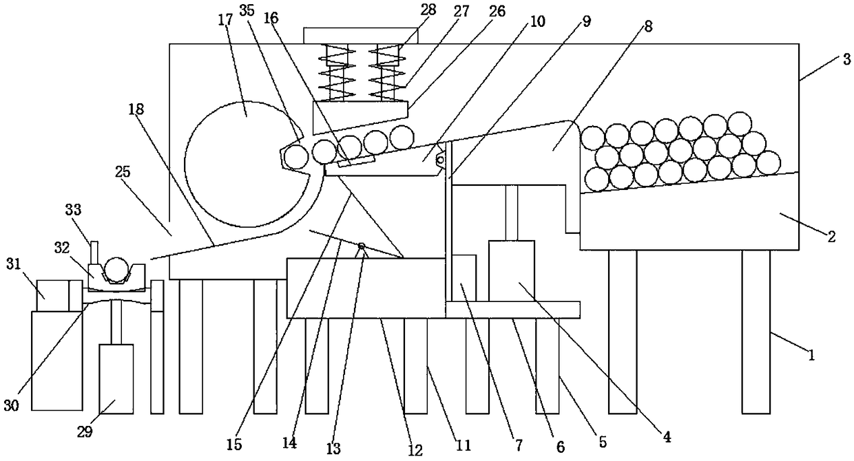
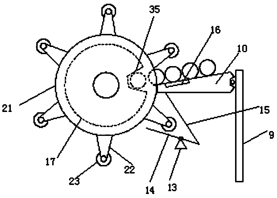
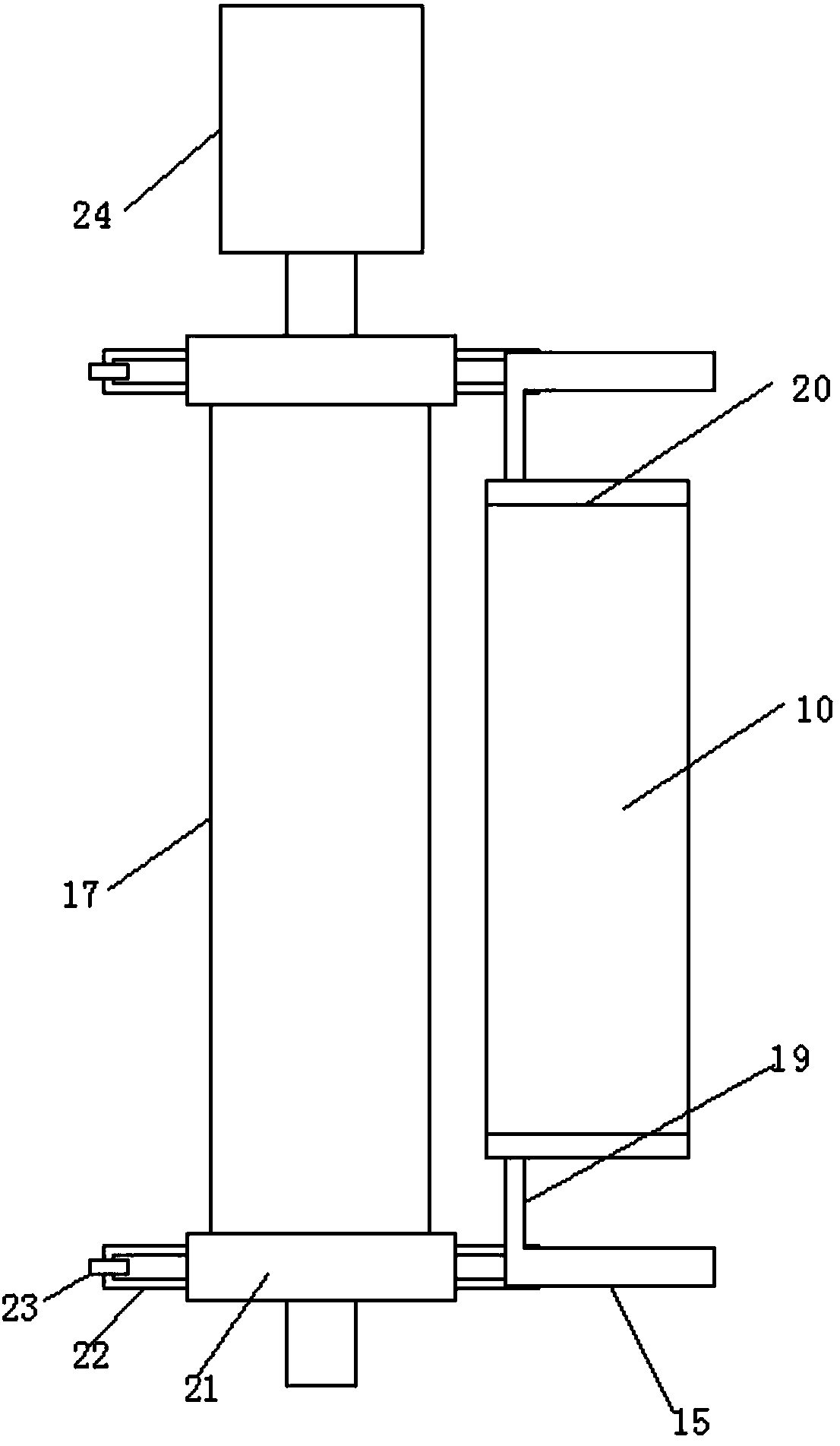
[0020] like Figure 1 to Figure 5 As shown, a steel pipe feeding device includes a conveying track 30, and the conveying track 30 is driven by a motor 31, and also includes a frame body 3, a controller 7, a material storage device, a feeding device, a feeding device and a material receiving device. device, one end of the feeding device is connected to the feeding device, the other end is connected to the storage device...


PUM


Abstract

The invention discloses a steel tube feeding device, and relates to the technical field of steel tube production. The steel tube feeding device comprises a conveying rail, a frame, a controller, a storage device and a supplementing device, a conveying device and a receiving device, the conveying rail is driven by a first motor, one end of the supplementing device is connected with the conveying device, the other end of the supplementing device is connected with the storage device, two ends of the frame are connected on the conveying device and the storage device, steel tubes are conveyed ontothe receiving device by the conveying device, the steel tubes are conveyed onto the conveying rail by the conveying device, the conveying device comprises a vibration device, and the controller is electrically connected with the supplementing device, the conveying device and the receiving device. According to the device, the steel tubes are automatically fed, labor intensity of operators is greatly reduced, working efficiency is improved, and potential safety hazards are avoided when the workers carry the steel tubes.

Description

technical field [0001] The invention relates to the technical field of steel pipe production, in particular to a steel pipe feeding device. Background technique [0002] Steel pipes are widely used in today's society, such as petrochemical industry and heat exchangers, etc. In conventional production, long steel pipes need to be cut into small sections by cutting machines, and due to the net weight of the steel pipe itself Larger and longer in length, it is very cumbersome to operate steel pipes during feeding and cutting. Most of the steel pipes are manually placed on the conveying track one by one, which increases the labor intensity of the operator and lowers the work efficiency. low, but there are also potential safety hazards. Contents of the invention [0003] The object of the present invention is to provide a steel pipe feeding device to solve the above-mentioned defects caused by the prior art. [0004] A steel pipe feeding device, including a conveying track, t...

Claims


Application Information

Patent Timeline
Patent Type & Authority Applications(China)
IPC IPC(8): B65G47/74B65G47/14
CPCB65G47/74B65G47/14B65G2201/0217B65G2203/044
Inventor 潘敬军
Owner 芜湖良匠机械制造有限公司
Why Eureka
Try Eureka