
Power consumption test device and method used for intelligent terminal

A smart terminal and power consumption testing technology, which is applied in the communication field, can solve the problems of inability to test the power consumption of the whole machine with a battery, limit the power consumption verification of R&D test personnel, and high test costs, so as to facilitate the production test process of the production line and realize the whole Machine power consumption test, convenient production line production test effect

Inactive Publication Date: 2018-09-18
GUANGDONG OPPO MOBILE TELECOMM CORP LTD
View PDF5 Cites 5 Cited by
  • Summary
  • Abstract
  • Description
  • Claims
  • Application Information

AI Technical Summary

Problems solved by technology

[0003] The inventors of the present application found that there are the following technical problems in the related technology: first, it is impossible to verify the power consumption before mass production in the factory, and it takes up manpower, resulting in low test efficiency and high test cost; second, it is limited to research and development testing The power consumption verification of personnel, and it is impossible to test the power consumption of the whole machine with battery, and the operation flexibility is poor; the third is that it only records the power consumption data, does not intercept or report abnormal power consumption data, and automatically checks the ability Difference

Method used


Image

  • Power consumption test device and method used for intelligent terminal
  • Power consumption test device and method used for intelligent terminal
  • Power consumption test device and method used for intelligent terminal

Examples


Embodiment Construction

[0040] Embodiments of the present invention are described in detail below, examples of which are shown in the drawings, wherein the same or similar reference numerals designate the same or similar elements or elements having the same or similar functions throughout. The embodiments described below by referring to the figures are exemplary and are intended to explain the present invention and should not be construed as limiting the present invention.

[0041] The device and method for testing power consumption of smart terminals according to the embodiments of the present invention will be described below with reference to the accompanying drawings.

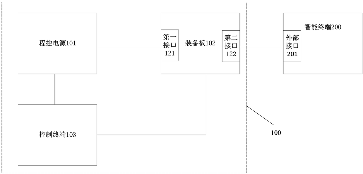
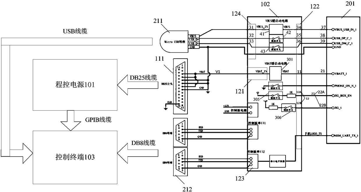
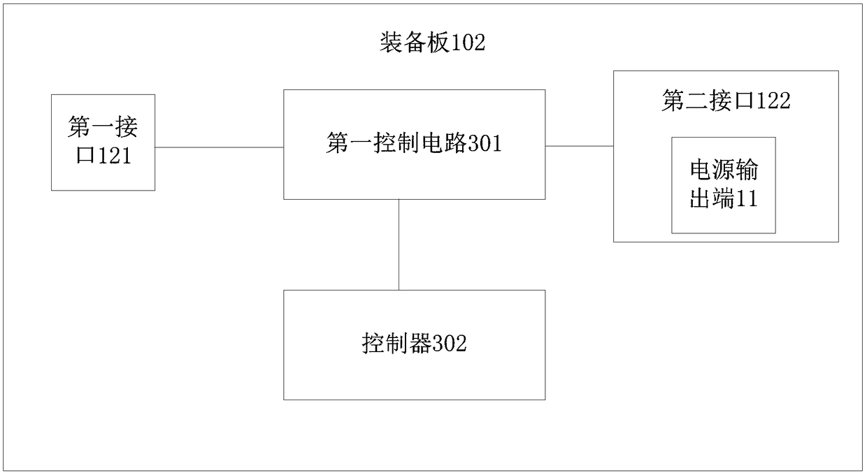
[0042] figure 1 It is a schematic block diagram of a power consumption test device for an intelligent terminal according to an embodiment of the present invention. Such as figure 1 As shown, the power consumption test device 100 for smart terminals includes: a programmable power supply 101 , an equipment board 102 and a control ...


PUM


Abstract

The invention provides a power consumption test device and method used for an intelligent terminal. The device comprises a program control power supply, an equipment plate and a control terminal. Theprogram control power supply is used for providing a first preset power supply. The equipment plate comprises a first port and a second port. The equipment plate is connected with the program controlpower supply through the first joint so as to receive the first preset power supply provided by the program control power supply. The equipment plate is also connected with an external port of the intelligent terminal through the second port. The equipment plate controls a cell of the intelligent terminal to stop providing power to a cell power supply end of the intelligent terminal through the second port during a power consumption test and providing the first preset power supply to the cell power supply end of the intelligent terminal through the second port. The control terminal is connected with the equipment plate. The control terminal is used for controlling the equipment plate to carry out power consumption test, acquiring power consumption data of the program control power supply and carrying out the power consumption test on the intelligent terminal according to the power consumption data of the program control power supply. Thus, the power consumption test of the whole machine with the cell can be achieved and the automation degree is high.

Description

technical field [0001] The present invention relates to the field of communication technologies, and in particular to a power consumption testing device for smart terminals, a power consumption testing method for smart terminals, and a non-transitory computer-readable storage medium. Background technique [0002] In related technologies, the power consumption of the smart terminal is usually tested by the following test method, that is, the dc power supply is connected to a dummy battery to supply power to the smart terminal, and the computer is connected to the dc power supply through the USB port to sample, record and calculate the output current of the dc power supply in real time. Therefore, the power consumption of the smart terminal can be monitored in real time. [0003] The inventors of the present application found that there are the following technical problems in the related technology: first, it is impossible to verify the power consumption before mass production...

Claims


Application Information

Patent Timeline
Patent Type & Authority Applications(China)
IPC IPC(8): G01R21/133
CPCG01R21/133
Inventor 白剑
Owner GUANGDONG OPPO MOBILE TELECOMM CORP LTD
Learn More