A test method for wall turbulence resistance of surface groove structure

A technology of turbulence resistance and testing method, which is applied in the detection field, can solve problems such as complex system, difficult clamping, and poor applicability, and achieve the effects of high energy consumption calculation accuracy, simple and reliable system, and convenient adjustment

Active Publication Date: 2020-02-07
WENZHOU UNIV
View PDF2 Cites 0 Cited by
  • Summary
  • Abstract
  • Description
  • Claims
  • Application Information

AI Technical Summary

Problems solved by technology

[0004] At present, there is no general standardized method for testing the drag reduction effect of liquid fluid on the solid surface groove structure. Generally, pipelines (water tunnels) or circulating water tanks are used. By setting the working section and the control section in parallel, the sample is placed in a certain working section. By testing the pressure, flow rate, and flow velocity at the inlet and outlet of the working section and the control section respectively, the data on the impact of different solid surface groove structures on the liquid flow pressure, flow, and flow velocity can be obtained, and then the different solid surface groove structures can be calculated. Drag reduction effect of liquid fluid on surface groove structure (relative percentage)
The characteristic of this type of test method is that the test sample is fixed during the test, and only the viscous resistance effect of the test sample surface relative to the incoming flow is measured, so it is highly dependent on stable and precise liquid flow control, and the corresponding pipeline (water hole) ) or the circulating tank system is complicated and costly, and the drag reduction detection of wall turbulent fluid such as superhydrophobic surface and bionic groove method is not easy to clamp and adjust, and the applicability is not good

Method used


Image

  • A test method for wall turbulence resistance of surface groove structure
  • A test method for wall turbulence resistance of surface groove structure

Examples


Embodiment 1

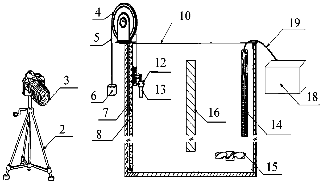
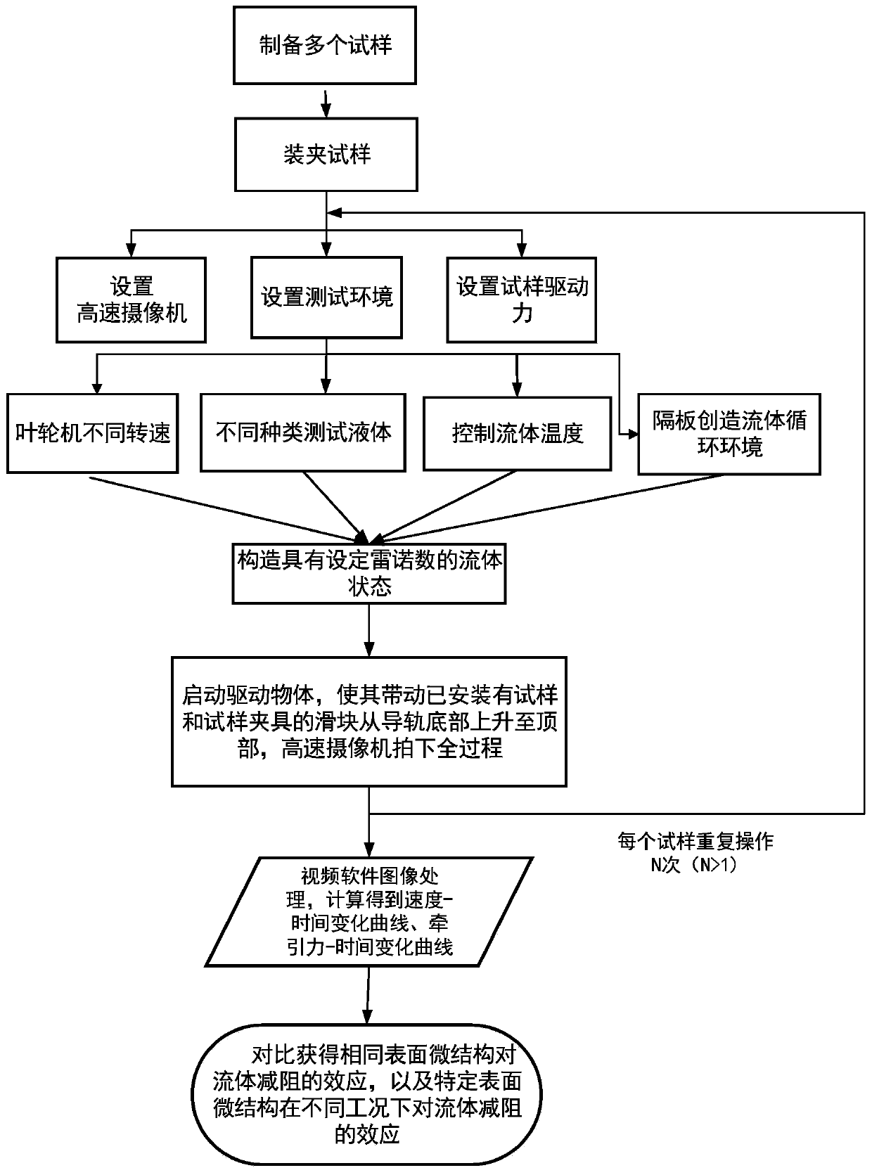
[0087] A method for testing wall turbulence resistance of a surface groove structure, specifically comprising the following steps:

[0088] (1) preparing a plurality of samples 13;

[0089] (1.1) The experimental equipment and processing parameters used are: ultraviolet laser with a wavelength of 355nm, a frequency of 55khz, a power of 1.6W, a scanning speed of 100mm / s, and scanning 10 times;

[0090] (1.2) Material and treatment process: 8 pieces of 304 stainless steel sheets with surface polishing were used in the experiment, with a specification of 4cm*4cm*1mm; one of them was a sample with no microstructure on the surface, which was used as the original control sample , and the remaining 7 single-sided laser etching prepared parallel groove patterns, and the scanning line spacing was 50, 80, 110, 140, 170, 200, 230 microns, and then the processed stainless steel surface was processed with a low surface energy reagent. Modification to obtain a micro-grooved surface with su...


PUM


Abstract

The invention provides a wall turbulence resistance testing method of a surface groove structure. The method comprises: a plurality of test samples are prepared, the test samples are installed, and initial conditions of the test are set; a sliding block is arranged to be at a test initial position; a high speed camera is started to start shooting; a driving object is started and thus the sliding block with the test sample and test clamp are driven to rise from the bottom of a guide rail to the top; real-time traction force values fed back by a force sensor of the driving object are recorded all the time; a test end position of the sliding block is recorded and shooting of the high speed camera is stopped; the test sample movement process shot by the high speed camera is analyzed and a traction-time changing curve is obtained; the above-mentioned steps are repeated by N times to obtain repeated N-times testing results of the test samples. Therefore, the precise testing of the fluid drag-reducing effect of the surface groove structure is realized; and the fluid drag-reducing effects of test samples of different surface groove structures under different fluid environment conditions atdifferent driving energy consumption, traction driving forces or traction speeds are tested.

Description

technical field [0001] The invention belongs to the technical field of detection, and in particular relates to a method for testing wall turbulence resistance of a surface groove structure. Background technique [0002] The component force of the fluid force that the object is subjected to against the direction of motion of the object or along the direction of the incoming flow velocity is called fluid resistance. Due to the viscous effect of the liquid, the surface of the object will produce a friction force tangent to the object surface, and the resultant force of all friction forces is called friction resistance. In the actual fluid, under the action of viscosity, not only frictional resistance will be generated, but also the surface pressure distribution will be different from that in the ideal fluid, and pressure differential resistance will be generated. The surface frictional resistance accounts for a large proportion of the total resistance of marine transportation ...

Claims


Application Information

Patent Timeline
Patent Type & Authority Patents(China)
IPC IPC(8): G01M10/00
CPCG01M10/00
Inventor 曹宇赵秀菊薛伟杨焕冯光吕永好李小刚
Owner WENZHOU UNIV
Why Eureka
Try Eureka