Fluid drag reduction effect test device for surface microstructure

A testing device and microstructure technology, applied in the field of detection, can solve the problems of complex system, difficult clamping, poor applicability, etc., and achieve the effects of high energy consumption measurement accuracy, simple and reliable system, and convenient adjustment.

Active Publication Date: 2018-11-16
WENZHOU UNIVERSITY
View PDF6 Cites 2 Cited by
  • Summary
  • Abstract
  • Description
  • Claims
  • Application Information

AI Technical Summary

Problems solved by technology
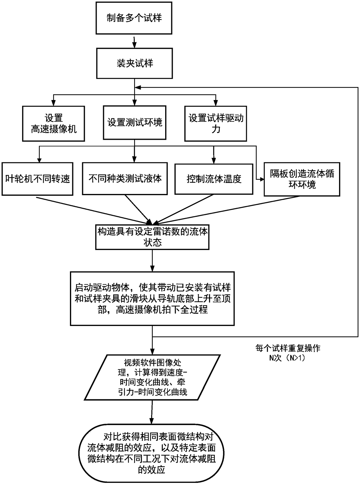
[0004] At present, there is no general standardized method for testing the drag reduction effect of liquid fluid on the microstructure of solid surfaces. Generally, pipelines (water tunnels) or circulating water tanks are used. By setting the working section and the control section in parallel, the sample is placed in a certain working section. Test parameters such as the pressure, flow rate, and flow velocity at the inlet and outlet of the liquid flow in the working section and the control section, and obtain comparable data on the impact of different solid surface microstructures on the liquid flow pressure, flow, and flow velocity, and then calculate the microstructure of different solid surface microstructures. Liquid fluid drag reduction effect of structure (relative percentage)
The characteristic of this type of test method is that the test sample is fixed during the test, and only the viscous resistance effect of the test sample surface relative to the incoming flow is measured, so it is highly dependent on stable and precise liquid flow control, and the corresponding pipeline (water hole) ) or the circulating tank system is complicated and costly, and the drag reduction detection of wall turbulent fluid such as superhydrophobic surface and bionic groove method is not easy to clamp and adjust, and the applicability is not good

Method used


Image

  • Fluid drag reduction effect test device for surface microstructure
  • Fluid drag reduction effect test device for surface microstructure

Examples


Embodiment Construction

[0030] In order to make the purpose, technical solutions and advantages of the embodiments of the present invention clearer, the technical solutions in the embodiments of the present invention will be clearly and completely described below in conjunction with the drawings in the embodiments of the present invention. Obviously, the described embodiments It is a part of the embodiments of the present invention, rather than all embodiments; the components of the embodiments of the present invention described and shown in the accompanying drawings generally can be arranged and designed in various configurations; below in conjunction with the accompanying drawings and specific Embodiments further describe the present invention in detail.

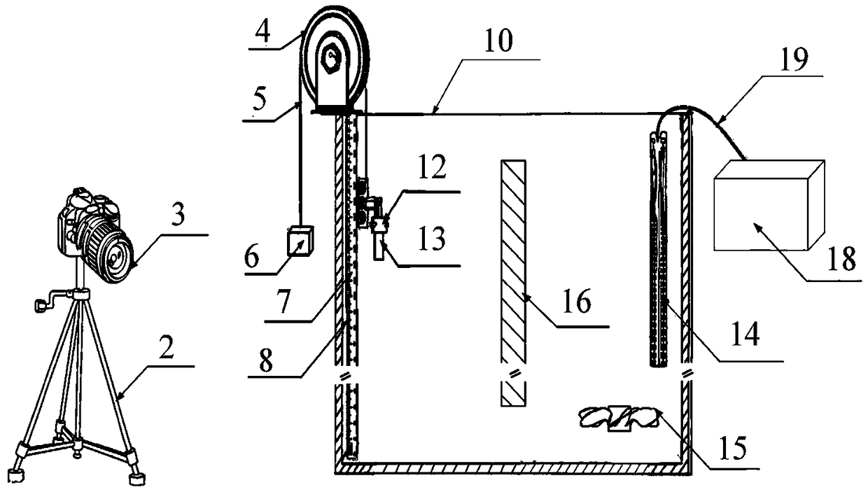
[0031] Such as figure 1 As shown, the present invention provides a test device for fluid drag reduction effect of surface microstructure, which includes an environment simulation unit, a motion control unit and a photographing and recording unit....


PUM


Abstract

The invention provides a fluid drag reduction effect test device for a surface microstructure. The device comprises an environment simulation unit, a motion control unit and a photographing and recording unit. The environment simulation unit comprises a tube, a turbine, a partition plate, a heating tube, a temperature controller and an external controller. The tube is a hollow container with an opening end and a closed end, is vertically arranged along the direction of gravity and is filled with a test liquid. The motion control unit comprises a guide rail slider mechanism, a sample clamper, apulley, a pulley rope and a driving object. The photographing and recording unit is a high-speed camera and is installed outside the tube so that the photographing and recording unit can clearly shoot the process of driving a sample to vertically upward move from the bottom along the gravity direction after focal length adjustment. The device realizes the accurate test on the fluid drag reductioneffect of a surface microstructure, can test fluid drag reduction effects of samples with different surface microstructures under different fluid environment conditions of different driving energy consumption, traction driving forces or traction speeds.

Description

technical field [0001] The invention belongs to the technical field of detection, and in particular relates to a fluid drag reduction effect testing device for surface microstructures. Background technique [0002] The component force of the fluid force that the object is subjected to against the direction of motion of the object or along the direction of the incoming flow velocity is called fluid resistance. Due to the viscous effect of the liquid, the surface of the object will produce a friction force tangent to the object surface, and the resultant force of all friction forces is called friction resistance. In the actual fluid, under the action of viscosity, not only frictional resistance will be generated, but also the surface pressure distribution will be different from that in the ideal fluid, and pressure differential resistance will be generated. The surface frictional resistance accounts for a large proportion of the total resistance of marine transportation tools...

Claims


Application Information

Patent Timeline
IPC IPC(8): G01N15/08
CPCG01N15/08
Inventor 曹宇赵秀菊薛伟杨焕冯光吕永好李小刚
Owner WENZHOU UNIVERSITY
Why Eureka
Try Eureka