
Novel pressing rod device of entertainment facility

A technology for amusement facilities and pressing rods, which is applied to entertainment devices, entertainment, slideways, etc., can solve the problems of cumbersome operation, time-consuming, loss of tourist benefits, etc., and achieves the effect of convenient and fast use and compact structure.

Pending Publication Date: 2018-09-18
GUANGDONG JINMA ENTERTAINMENT CORP LTD
View PDF6 Cites 3 Cited by
  • Summary
  • Abstract
  • Description
  • Claims
  • Application Information

AI Technical Summary

Problems solved by technology

In the industry standard of amusement equipment, it is stipulated that for amusement facilities with greater acceleration, there should be two sets of independent restraint devices for the passenger part, while the traditional restraint devices include a combination of shoulder pressure bar + independent safety belt + two-point safety belt. , in which the independent safety belt and the two-point safety belt require the operator to manually adjust repeatedly according to the body shape of the tourists. When there are two trains (trucks) running, if the first train (truck) takes a long time to board passengers, it will cause the rear train (truck) to stay, and the time is not fully utilized, which inhibits the increase of passenger flow and reduces the The operating efficiency of amusement equipment not only fails to achieve the purpose of pursuing high efficiency in the amusement industry, but also causes serious losses to the benefits of tourists.

Method used


Image

  • Novel pressing rod device of entertainment facility
  • Novel pressing rod device of entertainment facility
  • Novel pressing rod device of entertainment facility

Examples


Embodiment Construction

[0024] Below in conjunction with accompanying drawing and specific embodiment the present invention is described in further detail:

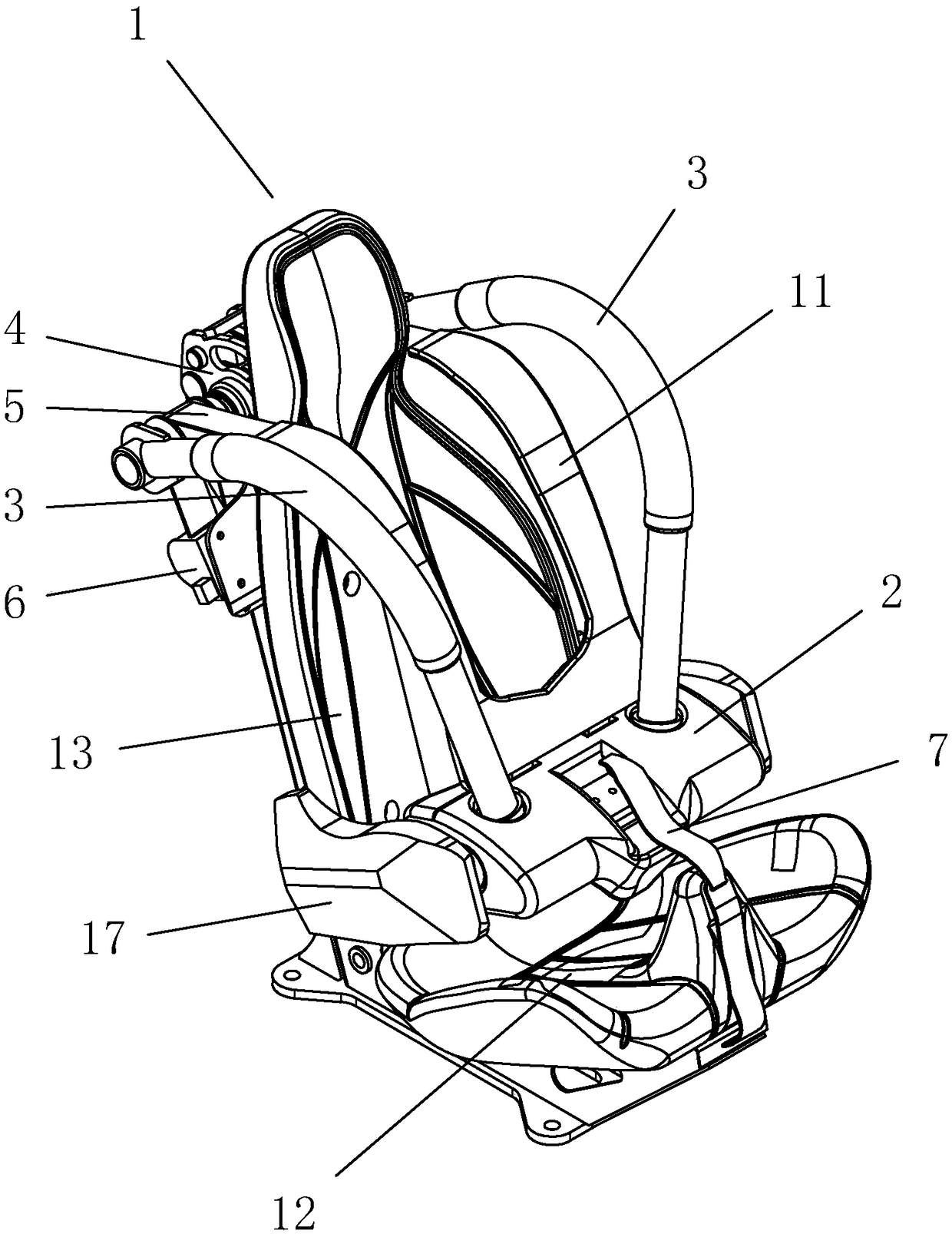
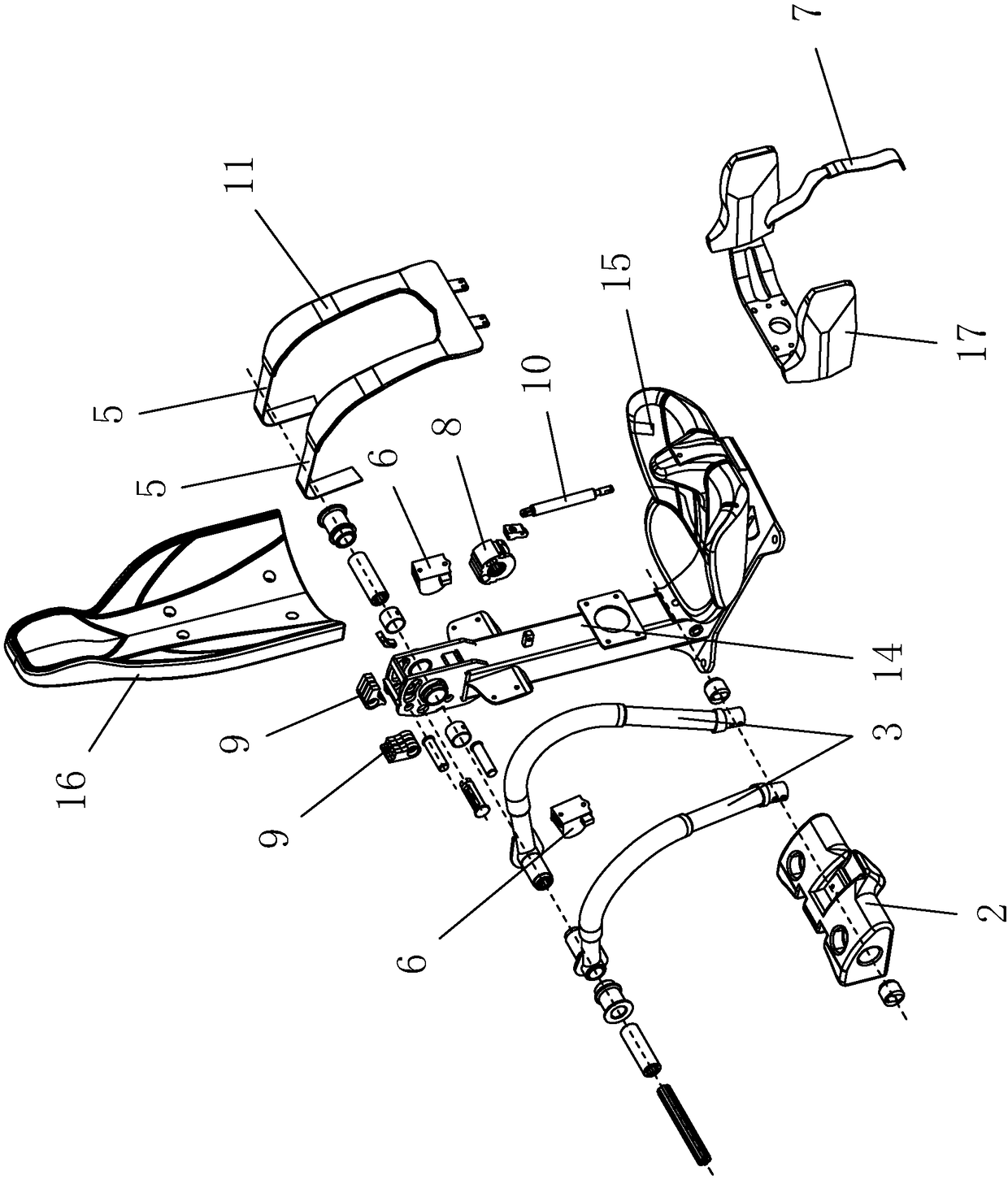
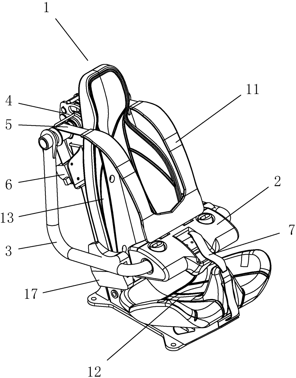
[0025] as attached figure 1 , attached figure 2 As shown, a new type of amusement equipment pressure bar device, including a seat 1, a leg pressing foam assembly 2 and a pressure bar 3 arranged on both sides of the seat 1, the seat 1 has a seat 12 and a back 13. The back 13 is provided with a self-locking mechanism 4 that allows one end of the pressing rod 3 to rotate or lock relative to it, and the other end of the pressing rod 3 is fixedly connected to the pressing leg foam assembly 2. The pressure bar device also includes first safety belts 5 arranged on both sides of the seat 1, one end of the first safety belt 5 is fixedly connected with the back 13 through the tightening mechanism 6, and the other end is fixed on the pressure belt. On the leg foam assembly 2, when the pressure bar 3 is pressed down, a space that can accommodate the uppe...


PUM


Abstract

The invention relates to a novel pressing rod device of an entertainment facility. The device comprises a seat, a leg pressing foaming assembly, pressing rods arranged on two sides of the seat and first safety belts arranged on two sides of the seat, the seat is provided with a sitting part and a back part, self-locking mechanisms used for allowing one ends of the pressing rods to rotate or lock relative to the back part are arranged on the back part, the other ends of the pressing rods are fixedly connected with the leg pressing foaming assembly, one ends of the first safety belts are fixedlyconnected with the back part through a tightening mechanism, the other ends of the first safety belts are fixed on the leg pressing foaming assembly, when the pressing rods are pressed, the first safety belts and the pressing rods are locked synchronously, a space capable of accommodating the upper part body of a player is formed in the part between the first safety belts and the back part, a space for the legs of the player to extend out is formed in the part between the leg pressing foaming assembly and the sitting part, the first safety belts are automatically tightened to adhere the bodyof the player by the tightening mechanism according to the body shape of the player, an operator does not need to repeatedly adjust the safety belts for players with different body shapes, player loading time is shortened to a greater extent, and the operating efficiency is effectively improved.

Description

【Technical field】 [0001] The invention relates to an amusement facility, in particular to a pressing bar device of the amusement facility. 【Background technique】 [0002] In order to ensure the safety of tourists when riding amusement equipment, the current amusement equipment is equipped with some safety devices. ACCIDENT. For example, the pressure bar device of a roller coaster seat has sufficient strength and locking force to ensure that tourists will not be thrown out or fall off, and it is always in a locked state before the equipment stops running. [0003] With the development of the amusement industry, both tourists and manufacturers have a higher pursuit of the operating efficiency of amusement equipment. In the industry standard of amusement equipment, it is stipulated that for amusement facilities with greater acceleration, there should be two sets of independent restraint devices for the passenger part, while the traditional restraint devices include a combinat...

Claims


Application Information

Patent Timeline
IPC IPC(8): A63G21/04
CPCA63G21/04
Inventor 陈朝阳王剑晖刘前佐何文标胡泽林王跃勇卢镇海刘情钟发声卢集雅付小康
Owner GUANGDONG JINMA ENTERTAINMENT CORP LTD
Learn More