Channel condition detection method, network equipment and user equipment
A technology of user equipment and network equipment, which is applied in the field of communication, can solve problems such as data transmission rate reduction, and achieve the effect of ensuring communication quality and communication efficiency
- Summary
- Abstract
- Description
- Claims
- Application Information
AI Technical Summary
Problems solved by technology
Method used
Image
Examples
Embodiment 1
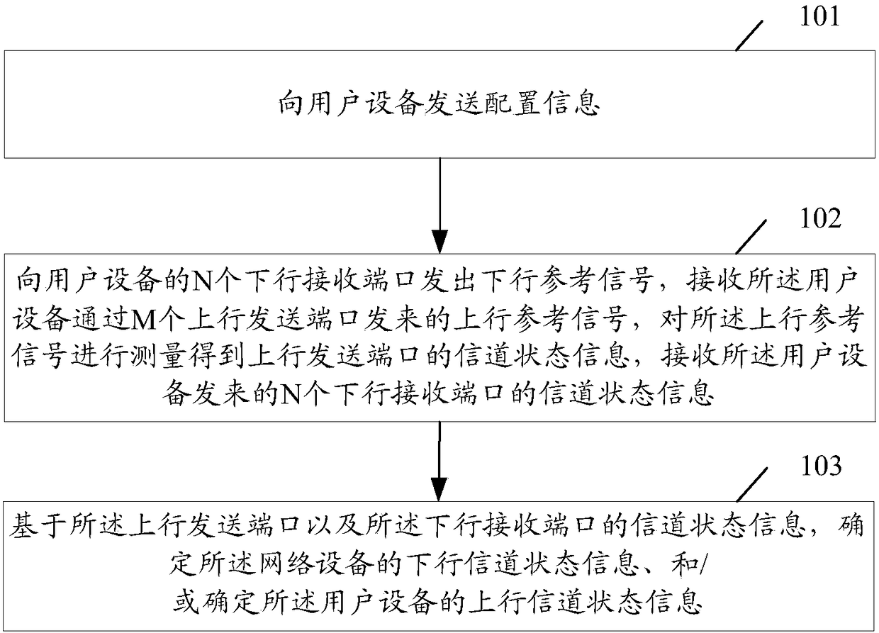
[0035] The embodiment of the present invention provides a channel state detection method, which is applied to network equipment, such as figure 1 Shown, including:
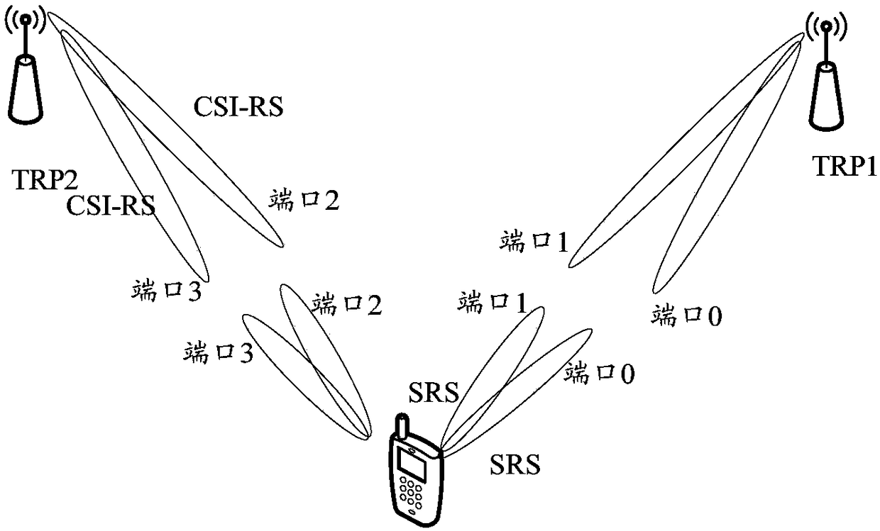
[0036] Step 101: Send configuration information to a user equipment, where the configuration information includes at least: information about M uplink transmission ports for the user equipment to send uplink reference signals, and information about N downlink reception ports for receiving downlink reference signals; the user The N downlink receiving ports of the device are at least partially different from the M uplink sending ports of the user equipment, and all the wireless ports of the user equipment are included in the N downlink receiving ports and the M uplink sending ports. In the set of ports; the wireless port is a port capable of uplink transmission and / or downlink reception; N and M are both integers greater than 0;
[0037] Step 102: Send downlink reference signals to N downlink reception ports of the user ...
example 2
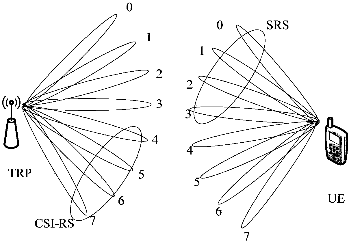
[0079] Example 2 of this embodiment, such as image 3 Shown, including:
[0080] In the 5G high-frequency mobile communication TDD system, assuming that the uplink and downlink channels are reciprocal, the beam management process determines the best transmission and reception beam pairing between TRP1 and UE, namely TRP CSI-RS transmit antenna port 0- 7 has a one-to-one correspondence with UE receiving antenna ports 0-7, and UE SRS transmitting antenna ports 0-7 and TRP receiving antenna ports 0-7 respectively. Limited by the UE's transmission capability, the UE can only transmit SRS based on beamforming on 4 antenna ports at the same time. In order to quickly all channel CSI information, the network side configures SRS in one or more uplink symbols of a time slot to transmit via ports 0-4, and at the same time configures CSI-RS to port in one or more downlink symbols in the time slot. 4-7 send, as shown in the figure. The UE measures the CSI-RS and reports part of the CSI meas...
Embodiment 2
[0102] The embodiment of the present invention provides a channel state detection method, which is applied to user equipment, such as Figure 4 Shown, including:
[0103] Step 401: Receive configuration information sent by a network device, where the configuration information includes at least: M uplink transmission port information for user equipment to send uplink reference signals, and N downlink reception port information for receiving downlink reference signals; The N downlink receiving ports of the user equipment are at least partially different from the M uplink sending ports of the user equipment, and all the wireless ports of the user equipment are included in the N downlink receiving ports and the M uplink sending ports In a port set consisting of ports; the wireless port is a port with uplink sending and / or downlink receiving functions; N and M are both integers greater than 0;
[0104] Step 402: Based on the configuration information, receive the downlink reference sign...
PUM
 Abstract
Description
Claims
Application Information
 - R&D
- Intellectual Property
- Life Sciences
- Materials
- Tech Scout
- Unparalleled Data Quality
- Higher Quality Content
- 60% Fewer Hallucinations
Browse by: Latest US Patents, China's latest patents, Technical Efficacy Thesaurus, Application Domain, Technology Topic, Popular Technical Reports.
© 2025 PatSnap. All rights reserved.Legal|Privacy policy|Modern Slavery Act Transparency Statement|Sitemap|About US| Contact US: help@patsnap.com


