Cable load measurement device and measurement method

A technology for measuring devices and cable loads, which is applied in the direction of measuring devices, measuring electrical variables, and measuring electricity, etc. It can solve the problems of not considering the influence of air and cable convection heat dissipation and contact thermal resistance, etc., and achieve the effect of convenient operation

Active Publication Date: 2018-09-14
陕西协成测试技术有限公司
View PDF8 Cites 7 Cited by
  • Summary
  • Abstract
  • Description
  • Claims
  • Application Information

AI Technical Summary

Problems solved by technology

[0005] The above-mentioned patent judges the load of the cable by detecting the temperature of the conductor, and does not take into account the convective heat dissipation between the air and the cable and the influence of contact thermal resistance

Method used


Image

  • Cable load measurement device and measurement method
  • Cable load measurement device and measurement method
  • Cable load measurement device and measurement method

Examples


Embodiment 1

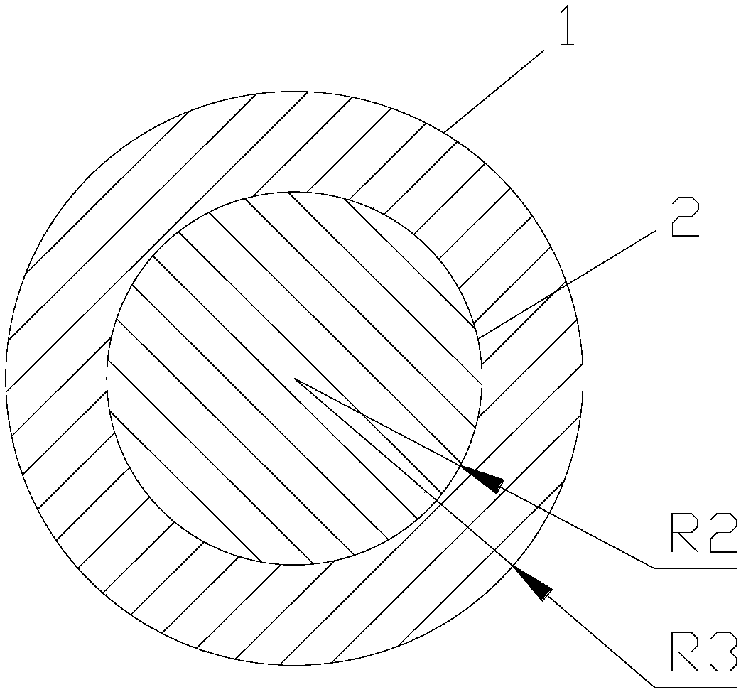
[0058] Cable dimensions such as figure 2 As shown, when the conductor 2 is Cu and the insulating layer 1 is PA66, the air convection heat dissipation coefficient α is 25W / m 2 ·K,R t =5500W / m K, λ t =0.3W / m·K, r 1 =0.003m, r 2 = 0.002m, resistance R per unit length Cu = 0.00137Ω, α = 25W / m 2 · K, substitute into formula (3) to get

[0059]

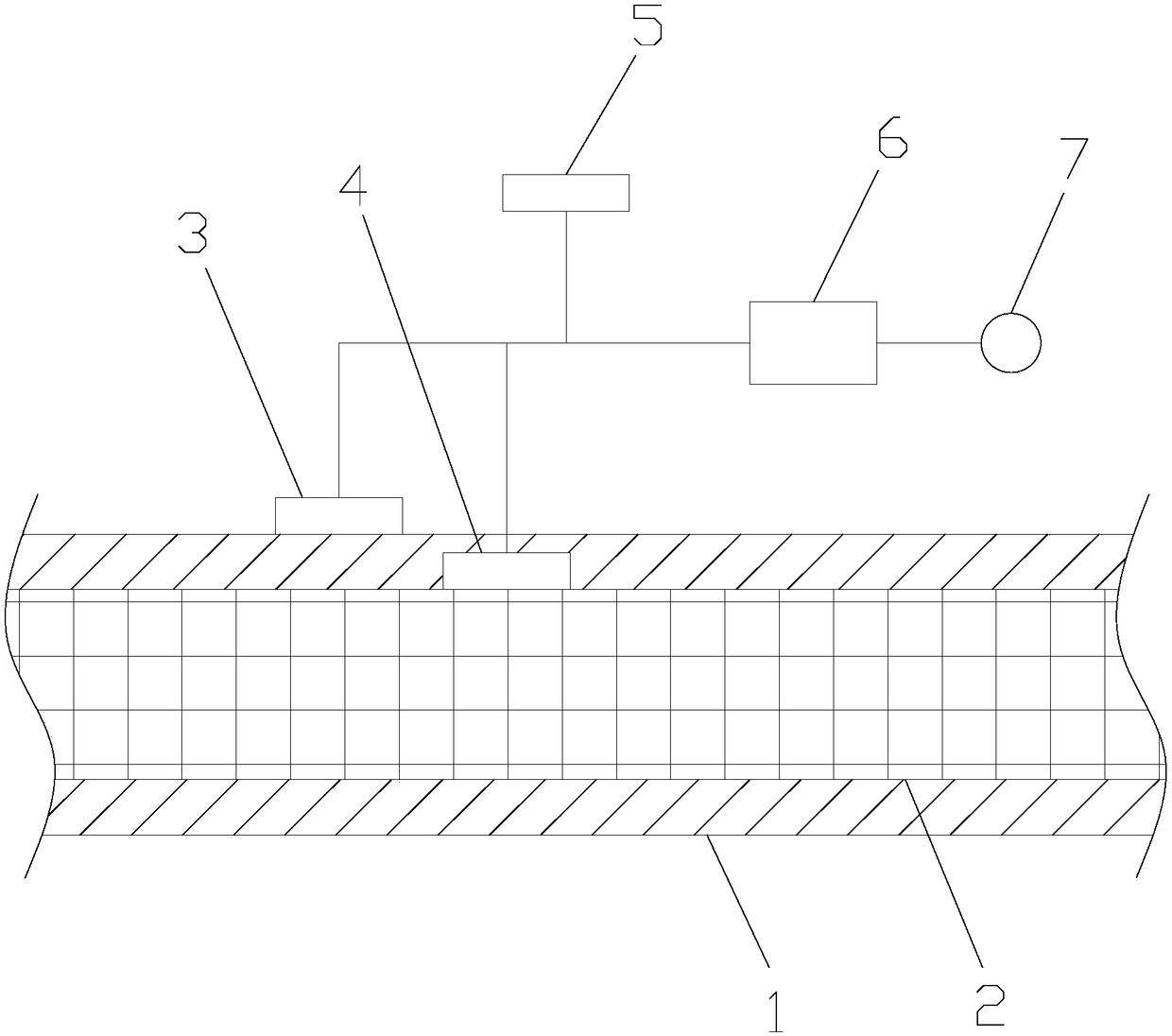
[0060] Set the temperature probe to a 3T 1 , temperature probe two 2T 2 The outer surface temperature of conductor 2 insulation layer 1, the temperature of conductor 2 and the ambient temperature measured by temperature probe 3 and 5 are brought into formula (4) respectively, and the working current I of conductor 2 can be calculated, and then the working current I of conductor 2 can be calculated with the rated current I of conductor 2 0 Compare if I > I 0 , then it shows that the cable is in an overload operation state at this time, and the controller 6 controls the alarm 7 to buzz to remind the staff to pay attention.

Embodiment 2

[0062] Cable dimensions such as figure 2 As shown, when the conductor 2 is made of aluminum and the insulating layer 1 is made of PA66, the air convection heat dissipation coefficient α is 25W / m 2 ·K,R t =4500W / m K, λ t =0.3W / m·K, r 1 =0.003m, r 2 = 0.002m, the resistance of aluminum per unit length R = 0.00222Ω, α = 25W / m 2 K, substitute into formula (3) to get

[0063]

[0064] The outer surface temperature T of conductor 2 insulation layer 1 measured by temperature probe 1 3, temperature probe 2 2 and temperature probe 3 5 respectively 1 , conductor 2 temperature T 2 and ambient temperature T c Putting them into formula (5) respectively, the working current I of conductor 2 can be calculated, and then the working current I of conductor 2 and the rated current I of conductor 2 0 Compare if I > I 0 , then it shows that the cable is in an overload operation state at this time, and the controller 6 controls the alarm 7 to buzz to remind the staff to pay attention. ...


PUM


Abstract

The invention discloses a cable load measurement device, and relates to the technical field of cable load measurement equipment. The cable load measurement device comprises a temperature probe I, a temperature probe II, a temperature probe III, a controller and an alarm, wherein the temperature probe I is fixed on the surface of an insulating layer; the temperature probe II penetrates through theinsulating layer and is in contact with the surface of a conductor; the temperature probe III is exposed to the air; and the controller is used for computing the temperature and load of the conductor.The invention further discloses a measurement method of the cable load measurement device. The device has the advantages that a relational expression among the working current of the conductor of a cable, the conductor temperature, the temperature of the outer surface of the insulating layer and environment temperature is derived according to the joule law and a heat conduction equation, furtherthe conductor temperature of the cable, the temperature of the outer surface of the insulating layer and the environment temperature are measured, the online real-time measurement of cable load is realized, and the device is convenient to operate, very safe and reliable, simple and efficient.

Description

technical field [0001] The invention relates to the technical field of cable load measuring equipment, in particular to a cable load device and a measuring method. Background technique [0002] The lights are bright and the lights are on. These words undoubtedly express the light brought by the lights to people, and the dazzling light needs the conduction of wires and cables. Wires are a tool for electrification in every family, but sometimes the wires purchased by users are biased. If the voltage of small or some electrical appliances is greater than the load of the wire, it is easy to cause the overload of the wire. Let me tell you about the hazards of overloading the wire and cable. Introduction The so-called overloading of wires is called "overloading". It's like a car with a load capacity of 1 ton, but the weight of the goods in transportation exceeds this regulation, it becomes "overload", which is not only easy to damage the vehicle. And it may also cause related tr...

Claims


Application Information

Patent Timeline
Patent Type & Authority Applications(China)
IPC IPC(8): G01R31/00
CPCG01R31/00
Inventor 王社兵
Owner 陕西协成测试技术有限公司
Why Eureka
Try Eureka