High-voltage direct current system rapid bypass series compensation device control method
A technology of bypass series compensation and high-voltage direct current, applied in the field of electric power, can solve the problems that affect the stable operation of the system, the problem of resonance and harmonic cannot be effectively solved, unstable harmonic resonance and other problems, and achieve the effect of convenient simulation analysis
- Summary
- Abstract
- Description
- Claims
- Application Information
AI Technical Summary
Problems solved by technology
Method used
Image
Examples
Embodiment 1
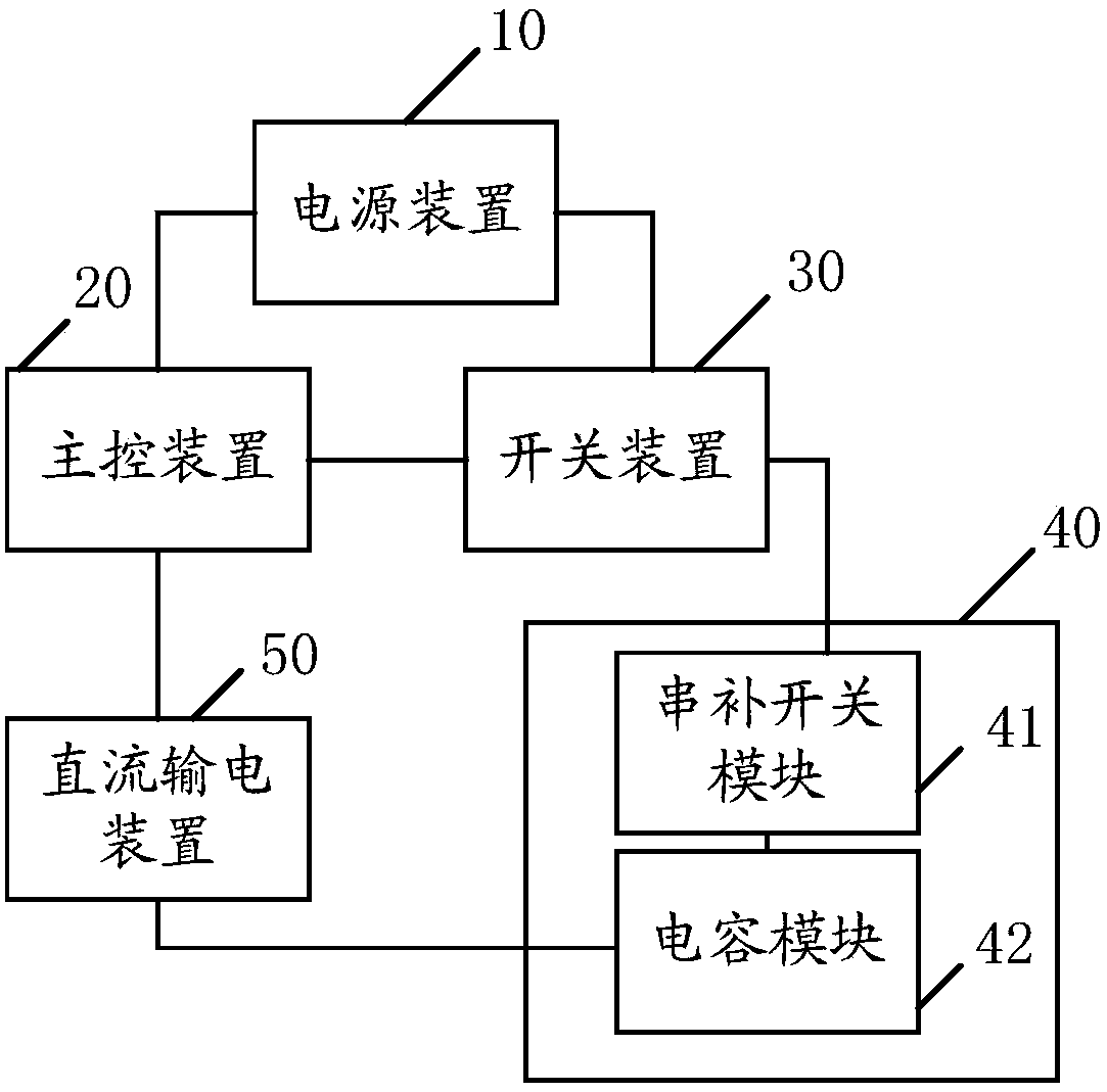
[0098] see figure 1 , an embodiment of the present invention provides a control method for fast bypass series compensation equipment in a high-voltage direct current system, including a power supply device 10, a main control device 20, a switch device 30, a series compensation device 40, and a direct current transmission device 50;
[0099] The output terminal of the power supply device 10 is respectively connected to the power supply terminal of the main control device 20 and the power supply terminal of the switching device 30;
[0100] The input end of the main control device 20 is connected to the output end of the direct current transmission device 50, and the output end of the main control device 20 is connected to the input end of the switching device 30;
[0101] The input end of the series compensation device 40 is connected to the output end of the switching device 30, and the series compensation end of the series compensation device 40 is connected to the series com...
Embodiment 2
[0132] see Figure 4 , the DC power transmission device 50 includes a DC pole control module 51, a DC station control module 52, a DC rectification side 53 and a DC inverter side 54;
[0133] The output terminal of the DC transmission device 50 is connected to the output terminal of the DC station control module 52, and the series compensation input terminal of the DC transmission device 50 is connected to the series compensation input terminal of the DC inverter side 54;
[0134] The first input terminal of the DC station control module 52 is connected to the power detection terminal of the DC rectification side 53 through the DC pole control module 51;
[0135] The output end of the DC rectification side 53 is connected to the input end of the DC inverter side 54 .
[0136] In this embodiment, the DC pole control module 51 is used to collect the DC voltage and DC current of the DC rectification side 53, and then transmit the DC voltage and the DC current to the The main co...
Embodiment 3
[0149] Embodiment three, on the basis of embodiment one,
[0150] see Image 6 , the DC power transmission device 50 further includes a DC protection module 55;
[0151] The first input terminal of the DC protection module 55 is connected to the power detection terminal of the DC inverter side 54 , and the output terminal of the DC protection module 55 is connected to the second input terminal of the DC station control module 52 .
[0152] In this embodiment, the DC protection module 55 is used to collect the voltage of the DC inverter side 54, and calculate the total harmonic distortion rate of the voltage on the DC protection module 55, or the collected The voltage is transmitted to the main control device 20, so that the main control device 20 calculates the total harmonic distortion rate of the voltage, which is not specifically limited in the present invention.
[0153] It should be noted that the judgment of whether the converter station is normal or not is based on th...
PUM
 Abstract
Description
Claims
Application Information
 - R&D
- Intellectual Property
- Life Sciences
- Materials
- Tech Scout
- Unparalleled Data Quality
- Higher Quality Content
- 60% Fewer Hallucinations
Browse by: Latest US Patents, China's latest patents, Technical Efficacy Thesaurus, Application Domain, Technology Topic, Popular Technical Reports.
© 2025 PatSnap. All rights reserved.Legal|Privacy policy|Modern Slavery Act Transparency Statement|Sitemap|About US| Contact US: help@patsnap.com


