
Determination method of reflection intensity at melting point of photonic crystal fiber ring based on otdr

A photonic crystal fiber, reflection intensity technology, applied in the measurement of refractive power, testing optical performance and other directions, can solve the problem of inability to measure the back-reflection light intensity of the melting point in the photonic crystal fiber optic gyroscope

Active Publication Date: 2019-11-12
BEIJING INST OF CONTROL ENG
View PDF8 Cites 0 Cited by
  • Summary
  • Abstract
  • Description
  • Claims
  • Application Information

AI Technical Summary

Problems solved by technology

[0007] The technical problem solved by the present invention is: to overcome the deficiency that the prior art cannot measure the back reflection light intensity of the melting point in the photonic crystal fiber optic gyroscope, and propose a method for determining the back reflection intensity of the melting point of the optical fiber ring of the photonic crystal fiber gyroscope based on OTDR

Method used


Image

  • Determination method of reflection intensity at melting point of photonic crystal fiber ring based on otdr
  • Determination method of reflection intensity at melting point of photonic crystal fiber ring based on otdr
  • Determination method of reflection intensity at melting point of photonic crystal fiber ring based on otdr

Examples


Embodiment Construction

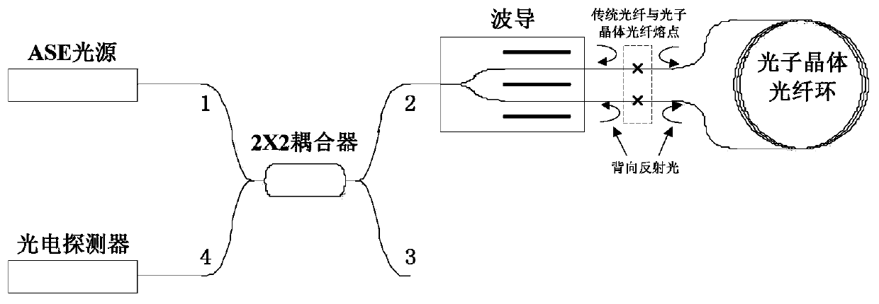
[0029] The photonic crystal fiber optic gyroscope is an angular velocity sensor based on the Sagnac effect. The basic principle is as follows: figure 1 As shown, the transmission path of the signal light wave is: the light emitted by the light source enters the coupler through port 1 of the 2×2 coupler, and outputs from the ports 2 and 3 of the coupler after beam splitting, and the port 2 of the coupler is connected to the input end of the waveguide. After entering the optical fiber ring through the waveguide, it interferes for a circle, and outputs from the waveguide, enters the coupler through the coupler 2 port, and outputs from the coupler 1 and 4 ports in reverse after the coupler splits the beam, and the coupler 4 port is connected to the detector , the output interference light wave enters the detector for detection. figure 1 At the same time, the back-reflected light wave generated by the melting point is marked, and its transmission path is the same as the output inte...


PUM


Abstract

The invention provides an OTDR-based photonic crystal fiber ring fusing point reflection intensity determining method. By fusing polarization maintaining optical fibers to two sides of a photonic crystal fiber and measuring the fusion point back reflection from the polarization maintaining optical fiber on one side by using an OTDR, back reflection of fusion points in a photonic crystal fiber ringcan be simulated, disturbance of gyro signal light to measurement can be suppressed, and independent measurement of back reflection can be realized. For solving the problem of low measurement precision of the OTDR, a non-fusion end face of the polarization maintaining optical fiber on the other side is cut to obtain an optical fiber cleavage surface perpendicular to the light transmission direction, and the surface becomes a Fresnel reflection surface which enables the back reflection intensity to be calculated accurately. With the back reflection light intensity relative ratio of the opticalfiber fusion points and the Fresnel reflection surface obtained from an OTDR measuring curve and the calculated absolute reflection intensity of the Fresnel reflection surface, the fusion point backreflection intensity can be obtained accurately. The method solves the problem that the fusion point back reflection intensity in a photonic crystal fiber ring cannot be measured and is high in measurement accuracy.

Description

technical field [0001] The invention relates to an OTDR-based method for determining the back reflection of the melting point of the photonic crystal fiber gyroscope fiber ring, which can realize the accurate measurement of the back reflection light intensity at the melting point of the photonic crystal fiber and the waveguide tail fiber in the photonic crystal fiber gyroscope, and belongs to the photonic crystal fiber Gyro technology field. Background technique [0002] Fiber optic gyroscopes have been widely used in space systems due to their all-solid-state, high-reliability, and high-precision characteristics. However, there is strong radiation in the space environment, and the rapid decline in performance and reliability of traditional optical fibers after irradiation seriously restricts the application of fiber optic gyroscopes. As a new type of material, photonic crystal fiber has substantially improved radiation resistance compared with ordinary fiber, and has the p...

Claims


Application Information

Patent Timeline
Patent Type & Authority Patents(China)
IPC IPC(8): G01M11/02
CPCG01M11/0228
Inventor 滕飞李勇杨博赵亚飞张宇飞林松张金保孙丽
Owner BEIJING INST OF CONTROL ENG
Learn More