
Energy-saving face identification device with automatic adjustment function

A face recognition and automatic adjustment technology, which is applied in the direction of supporting machines, mechanical equipment, machine platforms/supports, etc., can solve the problems of reducing the practicability of face recognition devices, easily affecting the judgment results of equipment, and consuming more power. Ease of shooting, flexible structure, and improved practicality

Inactive Publication Date: 2018-09-14
SHENZHEN XIAOKONG COMM TECH CO LTD
View PDF0 Cites 7 Cited by
  • Summary
  • Abstract
  • Description
  • Claims
  • Application Information

AI Technical Summary

Problems solved by technology

[0003] The installation height of the existing face recognition device is fixed, and because each person's height is different, during the recognition process, the person to be detected needs to adjust the pitch angle of the head according to his own height and the height of the recognizer , so that the camera can capture the human face, but in this way, there are different angles and inclinations between the camera and the human face, which will cause deviations in the images captured by the camera, which will easily affect the judgment results of the device. Not only that, but the existing human face Once the recognition device is turned on, no matter whether there is someone in front of the recognizer that needs to be detected, the recognizer keeps running with power consumption, which leads to the long-term operation of the recognizer and consumes more power, thereby reducing the existing face recognition. Availability of the device

Method used


Image

  • Energy-saving face identification device with automatic adjustment function
  • Energy-saving face identification device with automatic adjustment function
  • Energy-saving face identification device with automatic adjustment function

Examples


Embodiment Construction

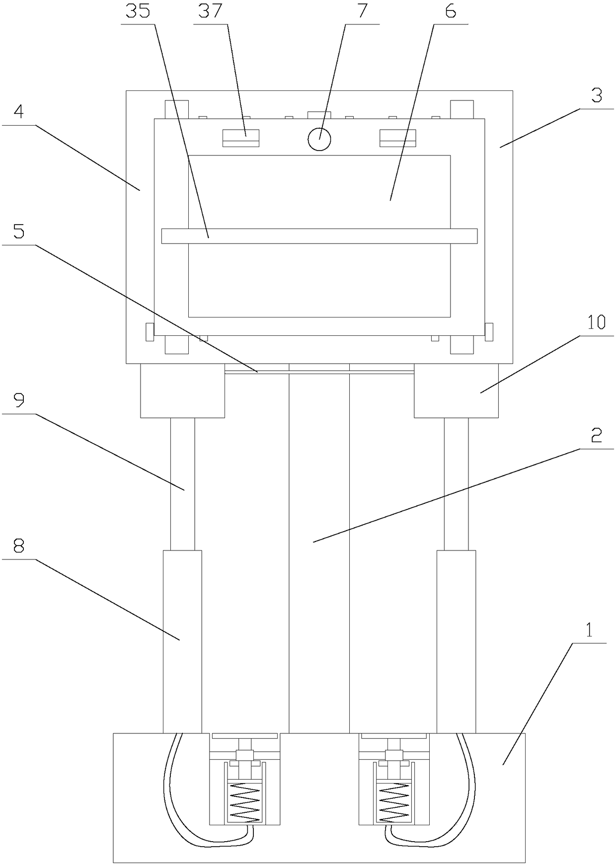
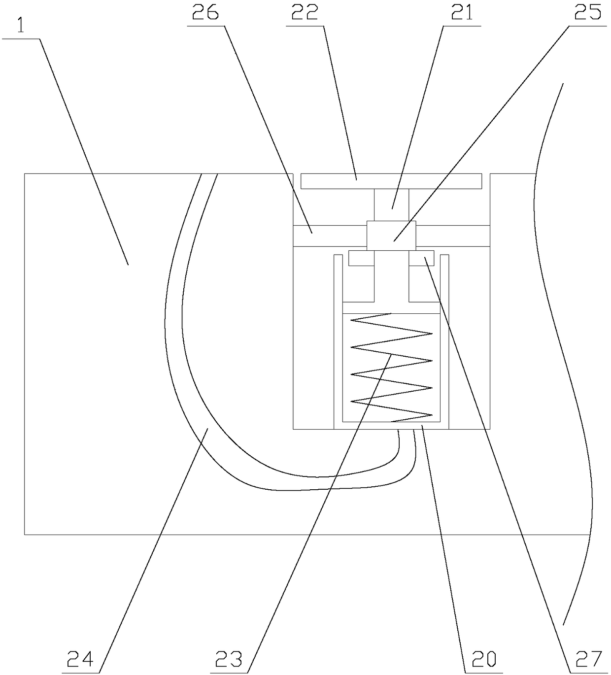
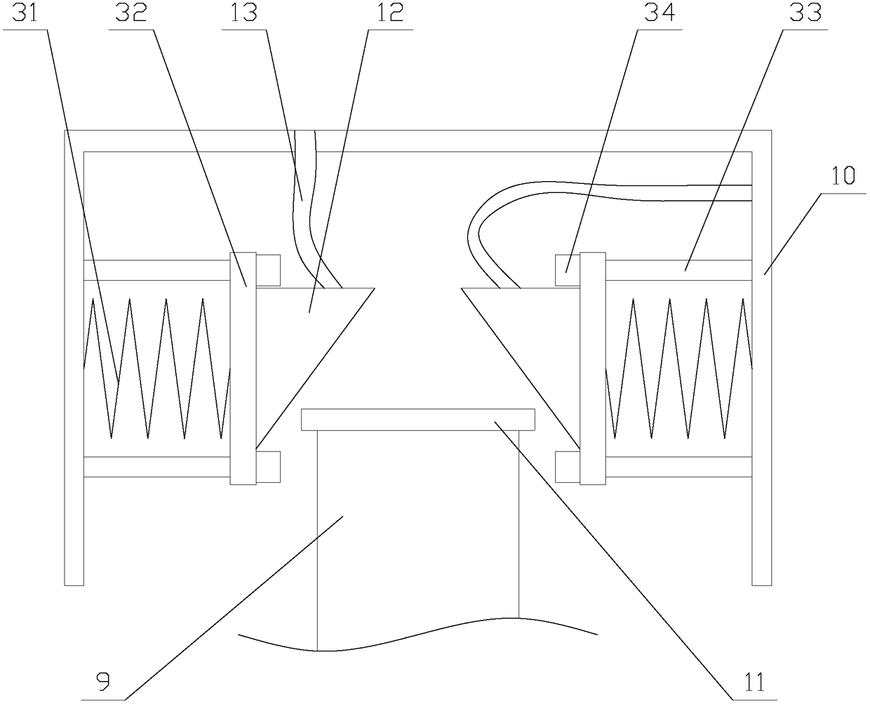
[0026] The present invention is described in further detail now in conjunction with accompanying drawing. These drawings are all simplified schematic diagrams, which only illustrate the basic structure of the present invention in a schematic manner, so they only show the configurations related to the present invention.

[0027] like figure 1 As shown, an energy-saving face recognition device with automatic adjustment function includes a base 1, a support board 2, a power supply board 3, an identifier 4, a first cable 5, a lifting mechanism and two trigger mechanisms, and the power supply The board 3 is fixed above the base 1 through the support board 2, the lifting mechanism is located between the power supply board 3 and the identifier 4, the lifting mechanism is connected to the identifier 4 in transmission, and the first cable 5 is located on the power supply board 3 Below, the two trigger mechanisms are respectively located at the two ends of the first cable 5, the identi...


PUM


Abstract

The invention relates to an energy-saving face identification device with an automatic adjustment function. The energy-saving face identification device comprises a base, a power supply plate, an identifier, a first cable, a lifting mechanism and two trigger mechanisms, the trigger mechanisms comprise trigger components, connecting components, first cylinders and first pistons, the connecting components comprise conductive boxes, conductive rods and two conductive units, the lifting mechanism comprises a motor, a connecting plate and two lifting components, and the lifting components compriseconveying belts, driven wheels, supporting units, driving shafts and driving wheels. The energy-saving face identification device with the automatic adjustment function can automatically control the identifier to be opened and closed through the trigger mechanisms according to a condition whether a user stands on a pedal or not, and the device avoids that redundant electric energy is consumed as the identifier is powered on when the user is absent, so that the device saves the energy. Compared with an existing trigger mechanism, the height of the identifier is adjusted by the lifting mechanism, a camera faces to the face of the user, a right face image is conveniently shot, and the face identification accuracy of the device is improved.

Description

technical field [0001] The invention relates to the field of face recognition equipment, in particular to an energy-saving face recognition device with an automatic adjustment function. Background technique [0002] Face recognition is a biometric technology for identification based on human facial feature information. A series of related technologies that use a video camera or camera to collect images or video streams containing human faces, automatically detect and track human faces in the images, and then perform facial recognition on the detected faces, usually also called portrait recognition and facial recognition. [0003] The installation height of the existing face recognition device is fixed, and because each person's height is different, during the recognition process, the person to be detected needs to adjust the pitch angle of the head according to his own height and the height of the recognizer , so that the camera can capture the human face, but in this way, ...

Claims


Application Information

Patent Timeline
Patent Type & Authority Applications(China)
IPC IPC(8): F16M11/24
CPCF16M11/24F16M2200/08
Inventor 齐进才
Owner SHENZHEN XIAOKONG COMM TECH CO LTD
Learn More