
Double-sided progressive double brake system

A braking system, a progressive technology, applied in the field of braking, can solve the problems of reducing the braking performance of the car, shortening the replacement time of the brake pads, and lack of driving safety.

Inactive Publication Date: 2018-09-14
朱敏
View PDF6 Cites 12 Cited by
  • Summary
  • Abstract
  • Description
  • Claims
  • Application Information

AI Technical Summary

Problems solved by technology

[0002] At present, the traditional braking technology uses the hydraulic system to push the brake pads and brake discs to achieve the braking effect of the car. The same brake pads are used for light braking and heavy braking. When the brake pads are rubbed for a long time, serious damage will occur. At this time, it is necessary to replace the brake pads in time to ensure effective braking, but in many cases, even if the car gives a reminder to replace the brake pads, due to some objective reasons, the brake pads cannot be replaced in time, and the severely worn brake pads still remain. It must continue to work. In this case, the braking performance of the car is seriously reduced, resulting in the lack of driving safety; in addition, the same brake pads are used for light braking and heavy braking. In order to make the brakes effective, the brake pads must have a strong The wear resistance of the same brake pad is used continuously, which will lead to faster wear of the brake pad, shorten the replacement time of the brake pad, increase the frequency of brake pad replacement, and increase the cost of the brake pad, so it is necessary to design a brake pad to increase safety. Braking system that can reduce the cost of brake pads

Method used


Image

  • Double-sided progressive double brake system
  • Double-sided progressive double brake system
  • Double-sided progressive double brake system

Examples


specific Embodiment approach

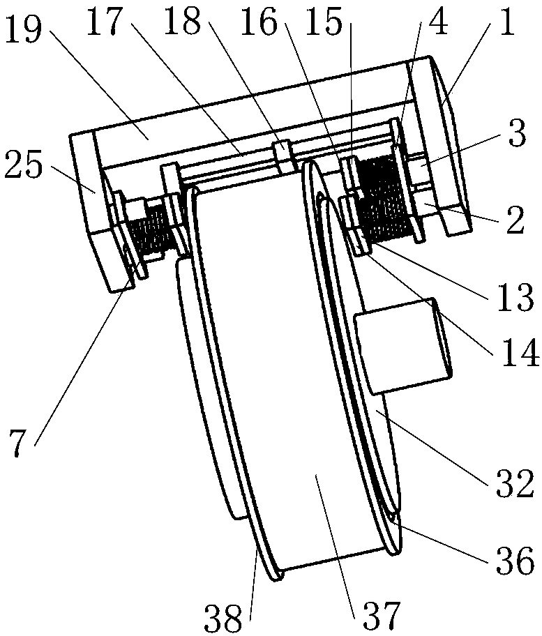
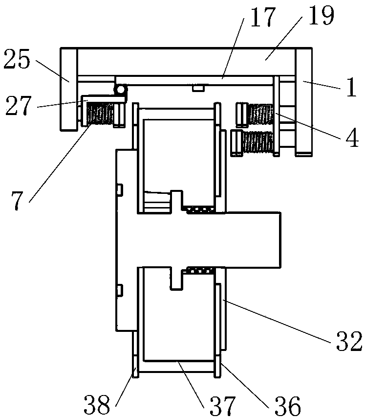
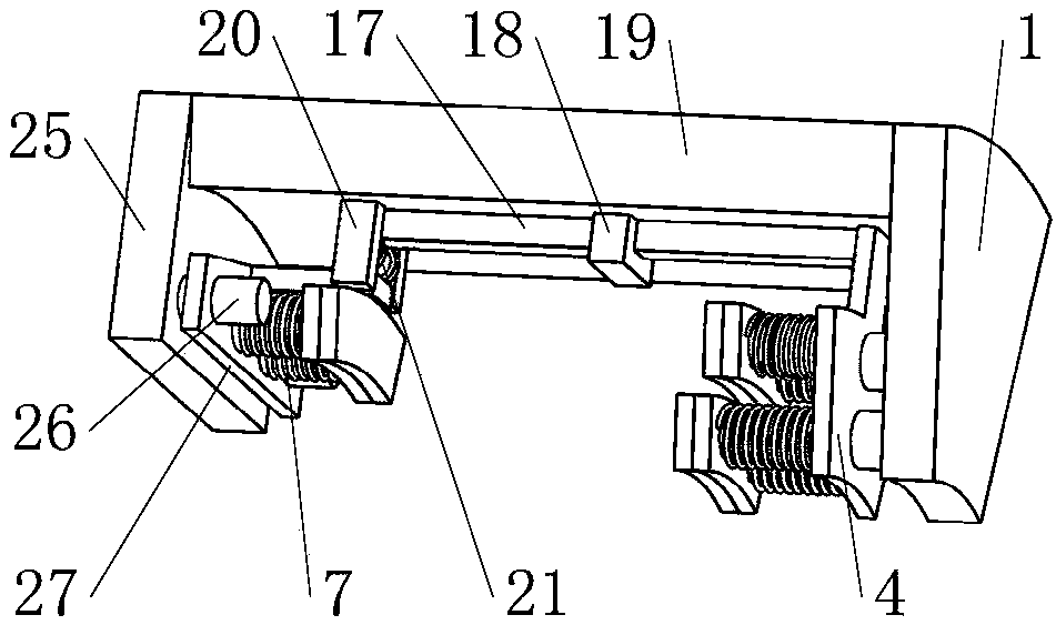
[0075] Specific embodiments: when the first hydraulic power column 2 and the second hydraulic power column 3 are not stretched by the hydraulic system, the first brake pad 14 and the first brake disc 32 do not contact and cause friction, and there is no braking effect at this time.

[0076] When the hydraulic system controls the extension of the first hydraulic power column 2 and the second hydraulic power column 3, the first hydraulic power column 2 and the second hydraulic power column 3 simultaneously push the first power plate 4, the first expansion rod 9, the second The telescopic rod 10, the first buffer spring 5, the second buffer spring 6, the first brake pad support 13, the first brake pad 14, the second brake pad support 15 and the second brake pad 16 move toward the first brake disc 32 together , at the same time, the first rack 17 moves in the same direction under the drive of the first power plate 4; the first rack 17 drives the first gear mechanism 21 to rotate th...


PUM


Abstract

The invention belongs to the technical field of braking, and particularly relates to a double-sided progressive double brake system. The system comprises a first brake mechanism, a connecting plate, aU-shaped support and a second brake mechanism, wherein the first brake mechanism is connected with an automobile hydraulic system. When the hydraulic system pushes the first brake mechanism to move toward a first brake disc, the first brake mechanism drives the second brake mechanism to move toward a third brake disc through a first gear mechanism; a first brake pad and the first brake disc firstgenerate friction, and light brake braking starts. The first brake pad continues to push a first brake disc mechanism to slide along a rotating shaft; the first brake disc mechanism drives a second brake disc mechanism to move to a second brake pad through a corresponding second gear mechanism, the second brake mechanism continues to move to the third brake disc and catches up with the third brake disc, then the second brake disc and the second brake disc generate friction, a third brake pad catches up with the third brake disc to generate friction, and the hard brake braking starts.

Description

technical field [0001] The invention belongs to the technical field of brakes, in particular to a double-sided progressive double brake system. Background technique [0002] At present, the traditional braking technology uses the hydraulic system to push the brake pads and brake discs to achieve the braking effect of the car. The same brake pads are used for light braking and heavy braking. When the brake pads are rubbed for a long time, serious damage will occur. At this time, it is necessary to replace the brake pads in time to ensure effective braking, but in many cases, even if the car gives a reminder to replace the brake pads, due to some objective reasons, the brake pads cannot be replaced in time, and the severely worn brake pads still remain. It must continue to work. In this case, the braking performance of the car is seriously reduced, resulting in the lack of driving safety; in addition, the same brake pads are used for light braking and heavy braking. In order t...

Claims


Application Information

Patent Timeline
IPC IPC(8): B60T1/06B60T13/12
CPCB60T1/065B60T13/12
Inventor 张良朱秀琼
Owner 朱敏
Learn More