
Omnidirectional wheel device, robot and control method of device

An omnidirectional wheel and control signal technology, applied in the field of robotics, can solve problems such as inability to real-time sub-wheel braking

Active Publication Date: 2018-09-14
BOE TECH GRP CO LTD
View PDF5 Cites 0 Cited by
  • Summary
  • Abstract
  • Description
  • Claims
  • Application Information

AI Technical Summary

Problems solved by technology

[0005] The present invention provides an omnidirectional wheel device, a robot and its control method to solve the problem in the prior art that the sub-wheels cannot be braked in real time during central braking

Method used


Image

  • Omnidirectional wheel device, robot and control method of device
  • Omnidirectional wheel device, robot and control method of device
  • Omnidirectional wheel device, robot and control method of device

Examples


Embodiment 1

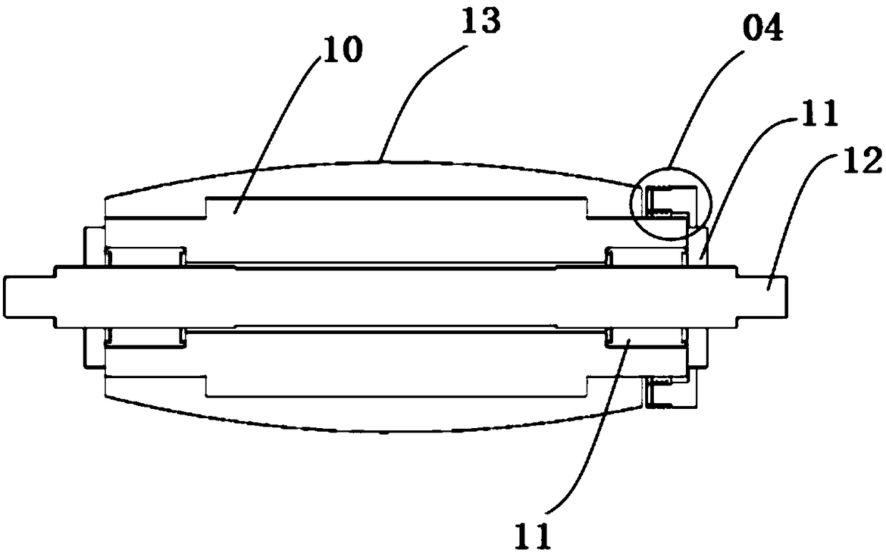
[0038] refer to figure 1 , shows a schematic structural view of an omnidirectional wheel device provided by an embodiment of the present invention. The omnidirectional wheel device may include: a main shaft 01, a center wheel (not shown in the figure), several sub-wheels 03, and a sub-wheel fixing plate 02 And conductive parts 05.

[0039] like figure 1 As shown, the center wheel and sub-wheel fixing plate 02 are sleeved on the main shaft 01 , and the center wheel and sub-wheel fixing plate 02 can rotate around the main shaft 01 . Several sub-wheels 03 are arranged along the outer circumference of the center wheel, and the sub-wheels 03 are connected between the two sub-wheel fixing plates 02, and each sub-wheel 03 can rotate relative to the center wheel.

[0040] One end of the main shaft 01 is also provided with a conductive component 05, the conductive component 05 is located on the side of the sub-wheel fixing plate 02 away from the center wheel, and the sub-wheel 03 is ...

Embodiment 2

[0064] refer to Figure 5 , which shows a flow chart of steps of a control method provided by an embodiment of the present invention, which may specifically include:

[0065] Step 501: Judging whether each sub-wheel satisfies a preset braking condition.


PUM


Abstract

The invention provides an omnidirectional wheel device, a robot and a control method of the device. The omnidirectional wheel device comprises a main shaft, a center wheel, multiple sub-wheels, sub-wheel fixing plates and conductive components. The center wheel and the sub-wheel fixing plates sleeve the main shaft and can rotate around the main shaft, and the center wheel is located between the two sub-wheel fixing plates; the sub-wheels are arranged on the outer circumference surface of the center wheel and connected between the two sub-wheel fixing plates; the conductive components are further arranged at the ends of the main shaft and located at the sides, away from the center wheel, of the sub-wheel fixing plates, and braking components are arranged at the sides, close to the conductive components, of the sub-wheels and coupled to the conductive components; the conductive components are configured to send control signals to the braking components of the designated sub-wheels; the braking components are configured to brake the sub-wheels which the braking components belong to when receiving the control signals sent by the conductive components. According to the omnidirectional wheel device, the corresponding sub-wheels are controlled to stop rotating by the braking components, and accordingly the precision of braking the sub-wheels is controlled.

Description

technical field [0001] The invention relates to the field of robots, in particular to an omnidirectional wheel device, a robot and a control method thereof. Background technique [0002] Wheeled mobile mechanisms have been widely used in mobile robots. Omni-directional wheel-based mobile mechanisms have unique characteristics that cannot be replaced by general wheel-based mobile mechanisms, and are of great significance for the study of robots' free walking. [0003] The omnidirectional wheel moving mechanism can include a central wheel and sub-wheels, and the sub-wheels can rotate freely. When the center wheel is braked, the sub-wheels will still rotate due to the inertia away from them, and the control precision of the sub-wheels is relatively low. [0004] Therefore, how to control the sub-wheels to stop rotating when braking centrally is a problem to be solved urgently at present. Contents of the invention [0005] The invention provides an omnidirectional wheel devi...

Claims


Application Information

Patent Timeline
IPC IPC(8): B60B19/12B60B33/00
CPCB60B19/125B60B33/0086B60B33/0092
Inventor 于占泉
Owner BOE TECH GRP CO LTD
Learn More