Design method of rotary mop dewatering device

A technology of dehydration device and rotary mop, which is applied to cleaning equipment, cleaning carpets, cleaning floors, etc., and can solve problems such as short use time and difficulty in replacing parts

Inactive Publication Date: 2018-09-14
LANZHOU JIAOTONG UNIV
View PDF5 Cites 0 Cited by
  • Summary
  • Abstract
  • Description
  • Claims
  • Application Information

AI Technical Summary

Problems solved by technology

[0008] To sum up, the existing problems in the prior art are: the rotary mop dehydration device in the prior art has a short service time and relatively difficult replacement of parts

Method used


Image

  • Design method of rotary mop dewatering device
  • Design method of rotary mop dewatering device
  • Design method of rotary mop dewatering device

Examples


Embodiment Construction

[0034] In order to make the object, technical solution and advantages of the present invention more clear, the present invention will be further described in detail below in conjunction with the examples. It should be understood that the specific embodiments described here are only used to explain the present invention, not to limit the present invention.

[0035] The application principle of the present invention will be further described below in conjunction with the accompanying drawings.

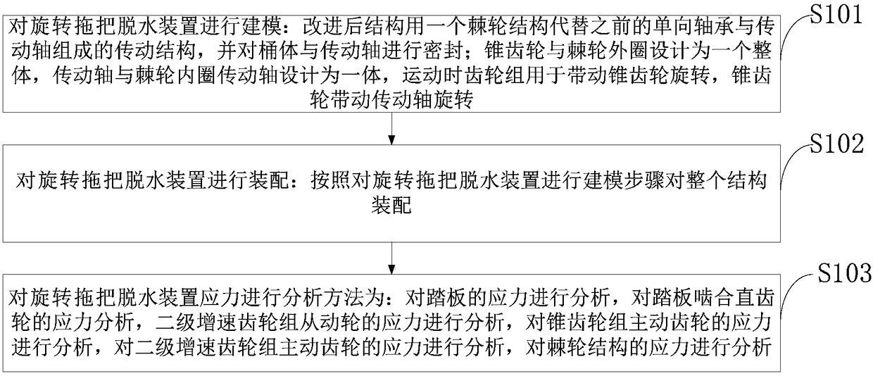
[0036] Such as figure 1 Shown: the design method of the rotary mop dehydration device that the embodiment of the present invention provides, comprises the following steps:

[0037] S101: Model the rotary mop dehydration device: the improved structure uses a ratchet structure to replace the previous one-way bearing and drive shaft, and seals the barrel and the drive shaft; the bevel gear and the outer ring of the ratchet are designed as As a whole, the drive shaft and the ratchet inner ...


PUM


Abstract

The invention discloses a design method of a rotary mop dewatering device. The design method includes: modeling a rotary mop dewatering device, assembling the rotary mop dewatering device, and performing stress analysis on the rotary mop dewatering device. The design method has the advantages that in order to solve the problems that an existing rotary mop dewatering device is short in service life, relatively hard in part replacement and the like, modeling of the existing entity is completed through three-dimensional modeling software on the basis of the existing rotary mop dewatering device,simulation movement of rotary mop dewatering device is achieved, and finite element stress analysis is performed on all the parts of the whole structure on the basis of the simulation movement; by static analysis and fatigue analysis in the finite element stress analysis, the most dangerous parts, affecting the service life of the device, in the parts and a transmission process are found, and themost dangerous parts are optimized to improve and optimize the device.

Description

technical field [0001] The invention belongs to the technical field of mop design, in particular to a design method of a rotary mop dehydration device. Background technique [0002] The dehydration devices that exist in the mop market at home and abroad mainly include: spin-drying barrels, water-squeezing devices for plates, and water-squeezing devices for rollers. There are many disadvantages such as disease prevention, easy to freeze fingers, etc. During the use of twisting water mop, just turn the handle on the upper part of the mop to effectively squeeze or wring out the water on the mop, which saves time and effort, and is fast and hygienic It can be seen that the use of dehydration tools can greatly improve the service life of the mop, and its sales market has become broader. Among them, the drying barrel is divided into: [0003] Foot-operated dehydration device; this kind of bucket is mainly driven by the user's foot pedal, exerting a force on the pedal, and transm...

Claims


Application Information

Patent Timeline
IPC IPC(8): A47L13/58
CPCA47L13/58
Inventor 任牟华刘潇潇车军勾刘晓慧
Owner LANZHOU JIAOTONG UNIV
Why Eureka
Try Eureka