Eureka AIR delivers breakthrough ideas for toughest innovation challenges, trusted by R&D personnel around the world.

Light wave wall-hanging stove

A wall-hung furnace and light wave technology, applied in lighting and heating equipment, fluid heaters, water heaters, etc., can solve problems such as electric shock accidents, electric leakage, and pipe bursts, so as to achieve safe and reliable use and avoid electric shock accidents , the effect of wide heat radiation area

Pending Publication Date: 2018-09-11
广东卓菲特新能源科技有限公司
View PDF1 Cites 1 Cited by
  • Summary
  • Abstract
  • Description
  • Claims
  • Application Information

AI Technical Summary

Problems solved by technology

[0003] In the prior art, there is an electric heating water tank inside the electric wall-hung boiler, and the electric heating water tank heats water through the electric heating tube installed inside. When working, the electric heating tube will contact with the water, and there will be a risk of leakage, especially if the electric heating tube is used for a long time. Burst phenomenon, more likely to produce leakage, easy to cause electric shock accidents

Method used


Image

  • Light wave wall-hanging stove
  • Light wave wall-hanging stove
  • Light wave wall-hanging stove

Examples


no. 1 example

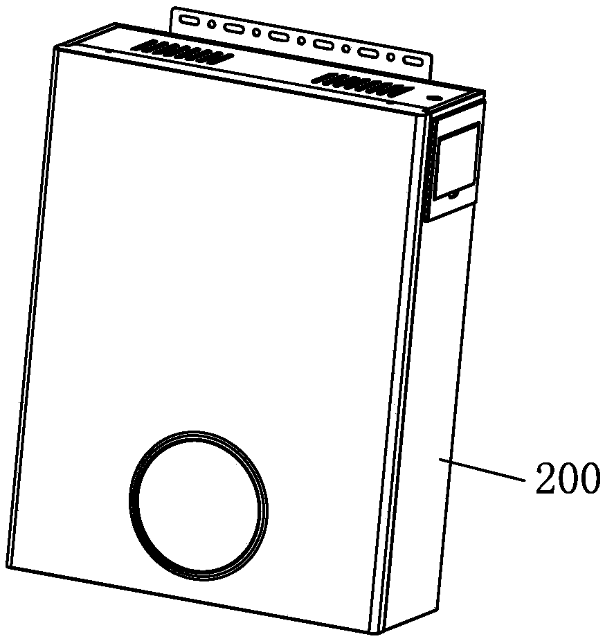
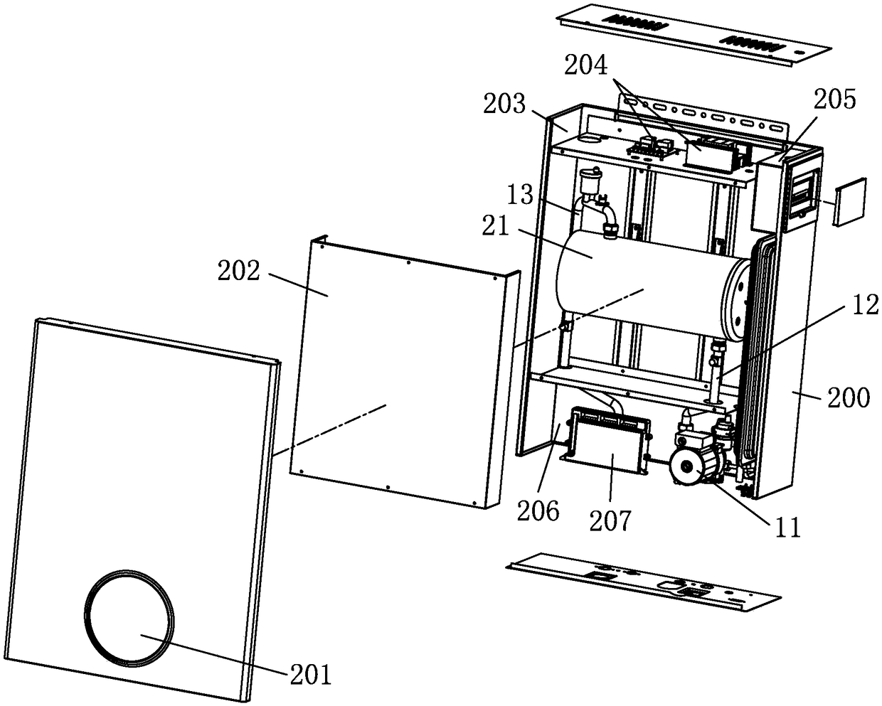
[0029] see Figure 1-Figure 7 , the light-wave wall-hung boiler includes a furnace body 200, the furnace body 200 is provided with a water inlet valve 10, a circulation pump 11, a water inlet pipe 12, an electric heating water tank, an outlet pipe 13 and a water outlet valve 14, which are sequentially connected to form a heating water circuit, When the present invention is working, tap water or heating water enters the electric heating water tank from the water inlet valve 10 and the water inlet pipe 12 under the action of the circulating pump 11, and is output to the water terminal through the water outlet pipe 13 and the water outlet valve 14 after passing through the electric heating water tank. or on the heating end.

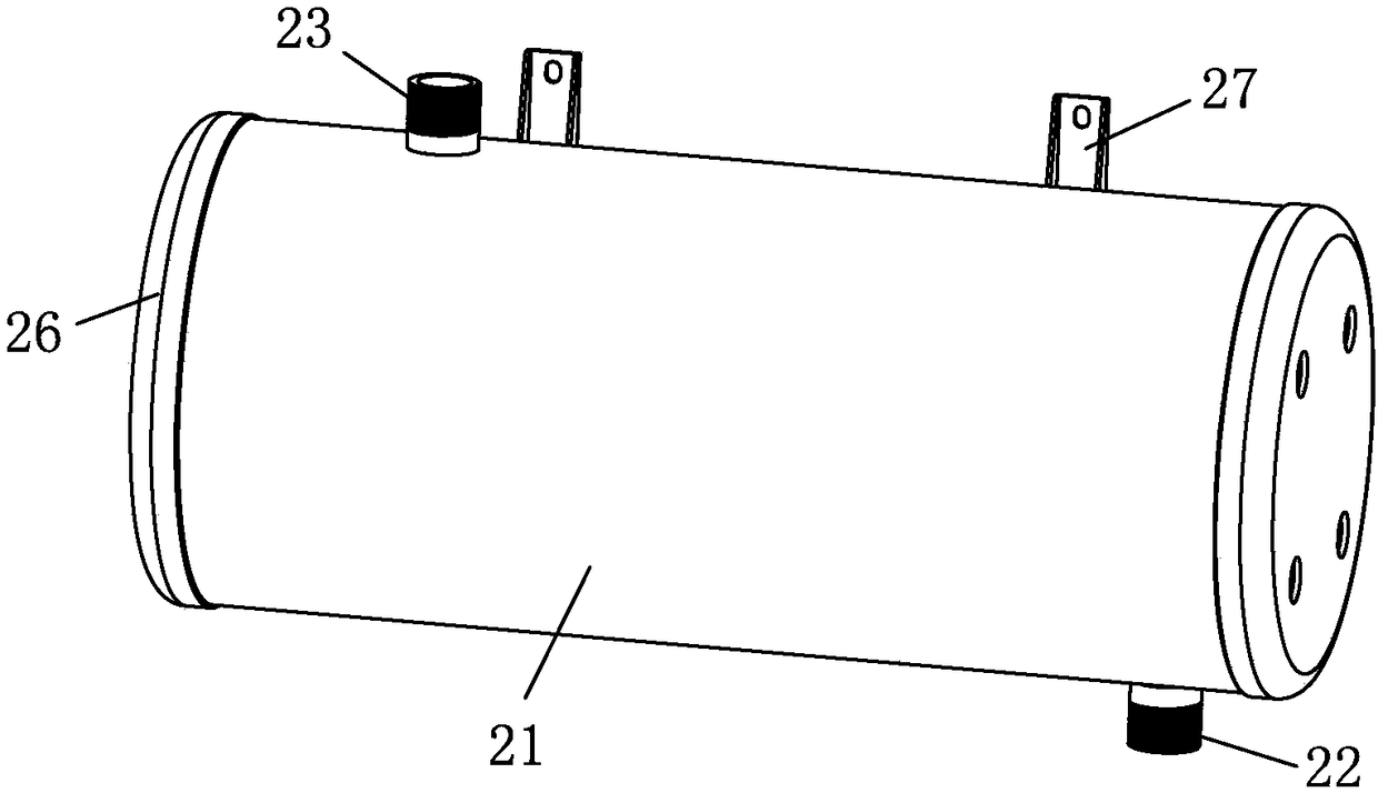
[0030] Wherein, the heating water tank of this embodiment is improved as follows, the heating chamber 25 is formed inside the heating box 21 for water circulation and heating; The water outlet 23 connected with the heating chamber 25 and the water outlet pi...

no. 2 example

[0041] The main difference between this heating water tank and the first embodiment is that there is one heating cylinder 24 installed in the heating box 21, which is arranged on the central axis of the heating box 21, and one set of light wave heating tubes is arranged in one heating cylinder 24 28, its actual heating power is relatively smaller, and this technical solution is more suitable for the household field.

[0042] Other unmentioned parts are the same as the first embodiment and will not be repeated.


PUM


Abstract

The invention discloses a light wave wall-hanging stove which comprises a stove body. The stove body is internally provided with a water inlet valve, a circulation pump, a water inlet pipe, an electrical heating water tank, a water outlet pipe and a water outlet valve which are sequentially connected to form a heating water way, a heating cavity for water circulation heating is formed inside a heating tank body, a water inlet communicating with the heating cavity and connected with the water inlet pipe is arranged at the lower portion, and a water outlet communicating with the heating cavity and connected with the water outlet pipe is arranged at the upper portion; a heating barrel is arranged in the heating tank body, a light wave heating tube is installed inside the heating barrel, heatgenerated when the light wave heating tube works is radiated to the surface of the heating barrel and is radiated to the interior of the heating tank body from the surface of the heating barrel, and water circulating in the heating cavity is heated. Heat generated when the light wave heating tube works is radiated to the surface of the heating barrel and is radiated outwards through the surface ofthe heating barrel, the water circulating in the heating cavity is heated, the light wave heating tube cannot be in contact with water due to blockage of the heating barrel, and true water and electricity separation is achieved.

Description

technical field [0001] The invention relates to a light-wave wall-hung boiler. Background technique [0002] Chinese Patent Document No. CN206247455U discloses a water-storage electric heating wall-hung boiler, which is composed of a shell, a water tank, an expansion tank, a plate heat exchanger, a water pump, a water flow sensor, and a controller. The water tank is made of metal or non-metal, with one or more built-in Electric heating tube, there is a metal or non-metallic casing outside the electric heating tube, the metal or non-metallic casing is tightly connected to the water tank, the casing is open at both ends, or one end is open and the other end is a blind tube; the electric heating tube is There is a heating wire in the non-metallic tube, and there are lead-out rods at both ends, or the heating wire is bent into a U shape in a non-metallic blind tube, and the two lead-out rods are led out at the same end. When bending into a U-shape, one must be isolated by an ins...

Claims


Application Information

Patent Timeline
Patent Type & Authority Applications(China)
IPC IPC(8): F24H1/20F24H9/18F24H9/20
CPCF24H1/201F24H9/1818F24H9/2021
Inventor 陈辉丕
Owner 广东卓菲特新能源科技有限公司
Why Eureka
Eureka Blog
Learn More