
Automatic transferring system and method for muck after manual pipe jacking

A technology of pipe jacking and dregs, applied in the direction of earth mover/shovel, construction, etc., can solve the problems of increasing construction cost, delaying construction period, low efficiency of manual excavation and transfer, etc., and achieve the effect of improving efficiency and saving manpower

Active Publication Date: 2018-09-11
湖北亘华工科有限公司
View PDF5 Cites 2 Cited by
  • Summary
  • Abstract
  • Description
  • Claims
  • Application Information

AI Technical Summary

Problems solved by technology

[0004] The purpose of the present invention is to overcome the deficiencies of the prior art, and the purpose is to provide an automatic transfer system and method for muck after manual pipe jacking, to solve the problem of low efficiency of manual excavation and transfer after the pipes are manually pushed into the ground section by section. Delay the construction period and increase the construction cost

Method used


Image

  • Automatic transferring system and method for muck after manual pipe jacking
  • Automatic transferring system and method for muck after manual pipe jacking
  • Automatic transferring system and method for muck after manual pipe jacking

Examples


Embodiment 1

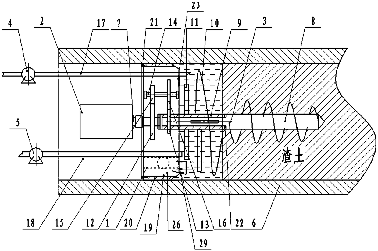
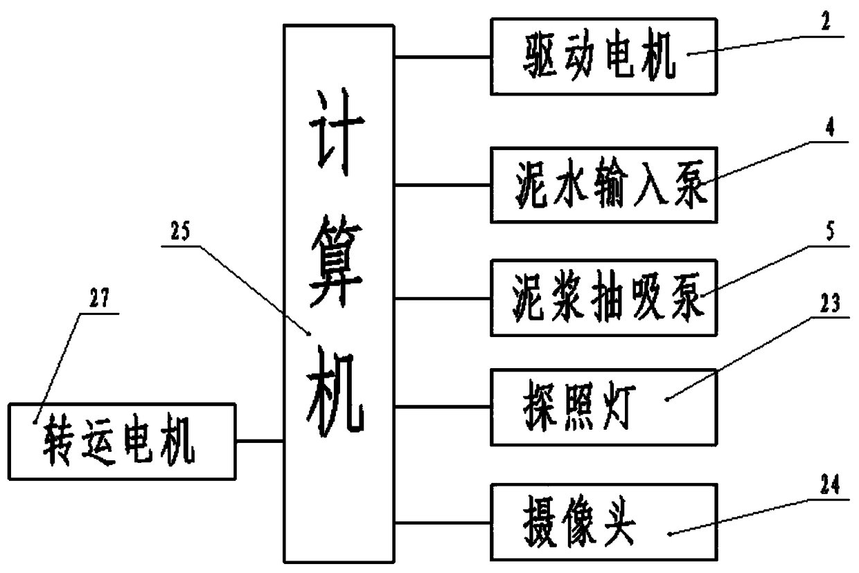
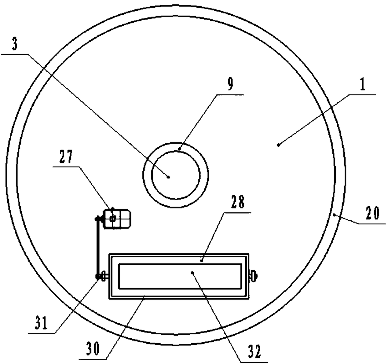
[0038] Such as Figure 1-3 As shown, the present invention is used for the automatic transfer system of slag after pipe jacking, comprising an annular sealing body 1, a driving motor 2, a rotating main shaft 3, a muddy water input pump 4 and a mud suction pump 5, and is characterized in that: the annular The sealing body 1 is placed in the jacking pipe, the ring surface of the annular sealing body 1 is sealed and connected with the inner wall of the jacking pipe 6, and a driving motor 2 is arranged on the outer middle part of the annular sealing body 1, and the outer end of the rotating main shaft 3 is sealed through the annular sealing body. The center of the body 1 is connected with the output shaft 7 of the drive motor 2, a feed drill bit 8 is provided on the inner end shaft of the rotating main shaft 3, and a rotating sleeve 9 is set in the middle of the rotating main shaft 3, and the rotating sleeve 9 The end is provided with soil loosening screw blade 10, and the rotatin...

Embodiment 2

[0054] Such as Figure 1-3 As shown, the present invention is used for the muck transfer method in the pipe after the underground artificial pipe jacking of the municipal environmental protection construction, including steps:

[0055] Step 1. Manually dig out the soil residue at the port of the jacking pipe 6, insert the annular sealing body 1 into the jacking pipe 6, the sealing rubber sleeve 20 of the annular sealing body 1 is sealed and bonded to the inner wall of the jacking pipe 6, and the front end of the annular sealing body 1 The feed drill bit 8 is inserted into the unexcavated soil in the pipe jacking 6;

[0056] Step 2: Start the drive motor 2, the muddy water input pump 4 and the mud suction pump 5 by controlling the computer 25;

[0057]Step 3: by rotating the feed drill bit 8 provided on the inner end shaft of the main shaft 3 to rotate in the soil residue, the annular sealing body 1 and the components arranged on the annular sealing body are driven to move for...


PUM


Abstract

The invention discloses an automatic transferring system and method for muck after manual pipe jacking. According to the automatic muck transferring system and method, a gravel transferring device isarranged in the lower side of an annular seal body, in the automatic transferring process of the muck after manual jacking, if a geological layer containing gravel is encountered, the annular seal body moves forwards along a jacking pipe, the gravel which cannot be stirred in the muck enter a transferring barrel which continuously rotate due to the extrusion force, the transferring barrel continuously rotate to quickly transfer the gravel on the inner side of the annular seal body to the outer side of the annular seal body, and meanwhile, the situation that muddy water on the inner side of theannular seal body cannot be circulated through a transferring channel can be guaranteed; and in the geological layer containing the gravel, if the gravel transferring device is not arranged, the inner side of the annular seal body cannot move forwards due to blocking of the gravel, and meanwhile, equipment can be damaged by the excessive gravel.

Description

technical field [0001] The invention relates to the technical field of municipal underground pipeline construction, in particular to an automatic transfer system and method for muck after manual pipe jacking. Background technique [0002] In pipeline laying construction, there are generally two methods: one is the open large-scale excavation method, that is, the ground is completely excavated to form pipe grooves, the pipes are connected to each other and placed in the pipe grooves, and then re-covered with soil to fill them up. This method of pipeline laying, the pipeline does not bear the effect of pressure or jacking force, that is to say, the pipeline laid by this excavation method does not need to consider the limitation of jacking force, and the construction is relatively simple and convenient. Another way is that due to the limitation of the construction location and environment, such as buildings, etc., it is not possible to use large excavation methods to lay pipeli...

Claims


Application Information

Patent Timeline
IPC IPC(8): E02F5/00E02F5/30E02F7/02
Inventor 杨佳志
Owner 湖北亘华工科有限公司
Learn More