
A lifting and horizontal transfer machine

A technology of lifting level and transferring machine, applied in the direction of conveyors, mechanical conveyors, conveyor objects, etc., to achieve stable work, reduce circuit complexity, and reduce the effect of motor load

Active Publication Date: 2019-07-09
WUHAN UNIV OF TECH
View PDF7 Cites 1 Cited by
  • Summary
  • Abstract
  • Description
  • Claims
  • Application Information

AI Technical Summary

Problems solved by technology

[0003] The purpose of the present invention is to solve the above-mentioned problems, and propose a lifting type horizontal transfer machine with simple structure and reliable performance, so as to solve the problem of the single double-speed chain at the entrance and exit of the aging room and the multi-layer double-speed chain inside the aging room. problem of connection between

Method used


Image

  • A lifting and horizontal transfer machine
  • A lifting and horizontal transfer machine
  • A lifting and horizontal transfer machine

Examples


Embodiment Construction

[0040] In order to better understand the above-mentioned technical solution, the above-mentioned technical solution will be described in detail below in conjunction with the accompanying drawings and specific implementation methods.

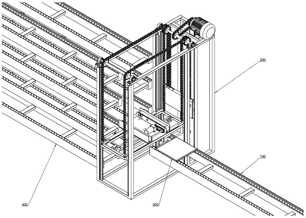
[0041] The application scenarios of the lifting and horizontal transfer machine provided by the embodiment of the present invention are as follows: figure 1 As shown, the lifting and horizontal transfer machine 200 provided by the present invention can effectively connect the single double-speed chain 100 at the entrance and exit of the aging room with the multi-layer double-speed chain 400 inside the aging room, and the tooling board 300 is conveyed by the single double-speed chain 100 .

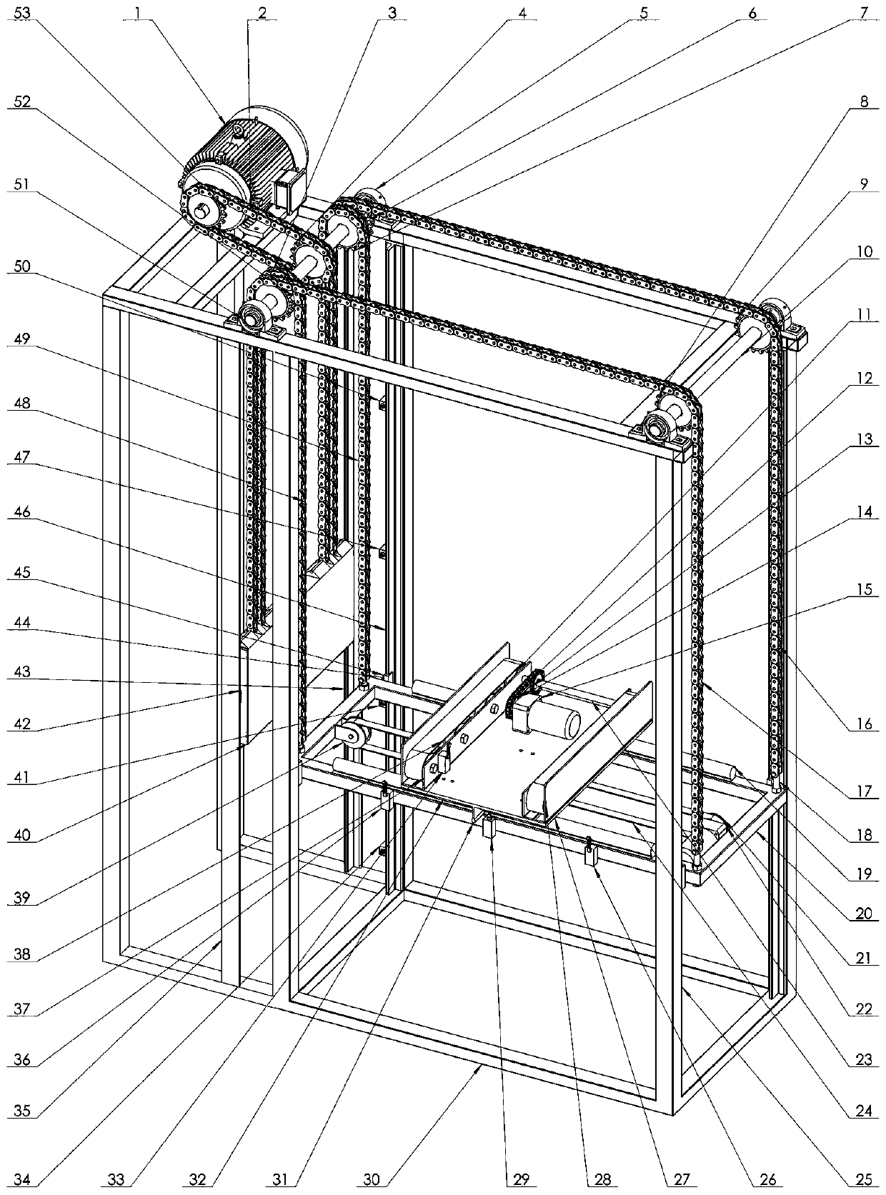
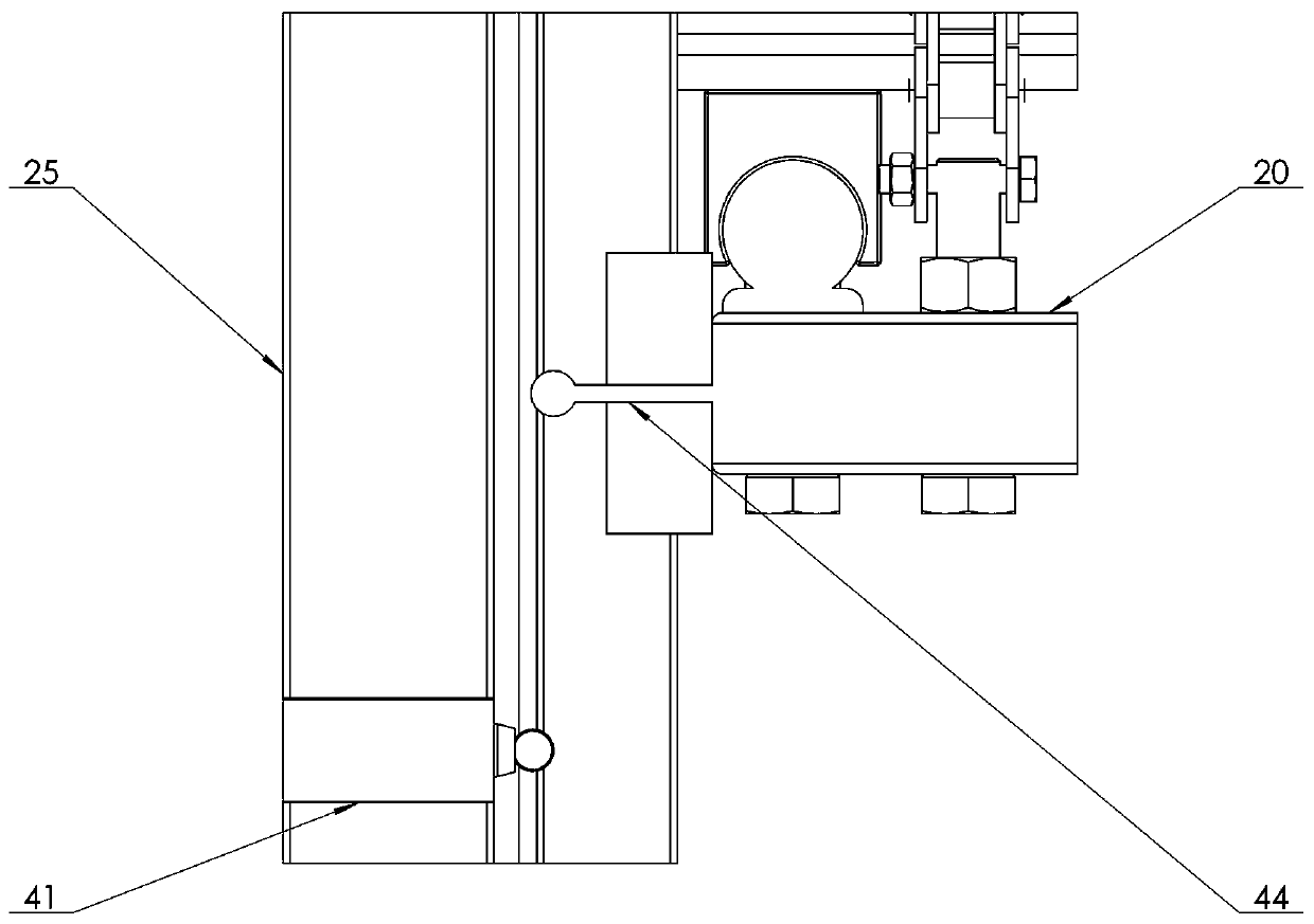
[0042] The structure of the lifting horizontal transfer machine provided by the embodiment of the present invention is as follows: figure 2 , image 3 , Figure 4 As shown, it includes a transfer machine support 30, a horizontal movement and a plate deliver...


PUM


Abstract

The invention belongs to the technical field of transferring machines and discloses a rising and falling horizontal transferring machine which comprises a transferring machine support, a rising and falling moving assembly and a horizontal moving and plate conveying assembly. A layer limit switch is arranged on the transferring machine support. The rising and falling moving assembly drives a risingand falling moving framework through a three-phase asynchronous band-type brake motor. The rising and falling moving framework is dragged through a chain. The horizontal moving and plate conveying assembly comprises a horizontal moving device and a plate conveying device. The horizontal moving device is provided with a horizontal limit switch, and a horizontal moving direct-current speed reducingmotor drives a horizontal moving bottom plate. The plate conveying device is provided with a plate in-place switch, and a plate conveying direct-current speed reducing motor drives a pattern conveying belt to drive a tool plate. The rising and falling horizontal transferring machine is simple in structure and reliable in performance, and the problem of connection between single triple speed chains of an inlet and an outlet of an aging house and multi-layer triple speed chain in the aging house can be solved.

Description

technical field [0001] The invention relates to the technical field of transfer machines, in particular to an elevating and horizontal transfer machine. Background technique [0002] In automotive electronic product manufacturing enterprises, the assembled electronic products need to undergo high-temperature aging tests, and the internal temperature of the aging room used for high-temperature aging tests is relatively high, and the interior is not suitable for manual long-term operation. In order to complete the aging process, the tooling boards carrying electronic products must be automatically transported outside the high-temperature aging room to the inside of the aging room for aging testing. After the set test time is reached, the working boards carrying electronic products will be sent out. If the number of products to be aged is small, a single double-speed chain can be used to send the tooling boards carrying electronic products into the aging room; if the number of ...

Claims


Application Information

Patent Timeline
Patent Type & Authority Patents(China)
IPC IPC(8): B65G43/00B65G37/00B65G17/26B65G23/06B65G23/22B65G47/64
CPCB65G17/26B65G23/06B65G23/22B65G37/00B65G43/00B65G47/643
Inventor 胥军苏田李文博
Owner WUHAN UNIV OF TECH
Learn More