
Spherical loudspeaker box shell joint polishing device of disc sliding type structure

A polishing device and a sliding technology, which is applied in the direction of grinding/polishing equipment, grinding machines, metal processing equipment, etc., can solve the problems that the roughness cannot meet the production requirements, the polishing effect is not good, and it is inconvenient to control, etc. Better effect, avoid excessive polishing, simple structure effect

Active Publication Date: 2018-09-11
嵊州市格瑞特电子有限公司
View PDF6 Cites 3 Cited by
  • Summary
  • Abstract
  • Description
  • Claims
  • Application Information

AI Technical Summary

Problems solved by technology

[0003] The shape of the speaker is square, spherical and irregular. The speaker is generally an injection molded part. After the injection molding is completed, one side of the injection molded part needs to be polished. The connection of the spherical speaker is basically treated by thermal compounding. At this time, its surface It is relatively rough, and its roughness cannot meet the production requirements, so it is necessary to polish the connection. The polishing treatment of the existing spherical speaker connection is generally through manual polishing, because it is inconvenient to control the polishing of the spherical speaker. The work efficiency is relatively low, the precision is low, and the polishing effect is not good, so it needs to be improved

Method used


Image

  • Spherical loudspeaker box shell joint polishing device of disc sliding type structure
  • Spherical loudspeaker box shell joint polishing device of disc sliding type structure
  • Spherical loudspeaker box shell joint polishing device of disc sliding type structure

Examples


Embodiment Construction

[0018] The technical solution of this patent will be further described in detail below in conjunction with specific embodiments.

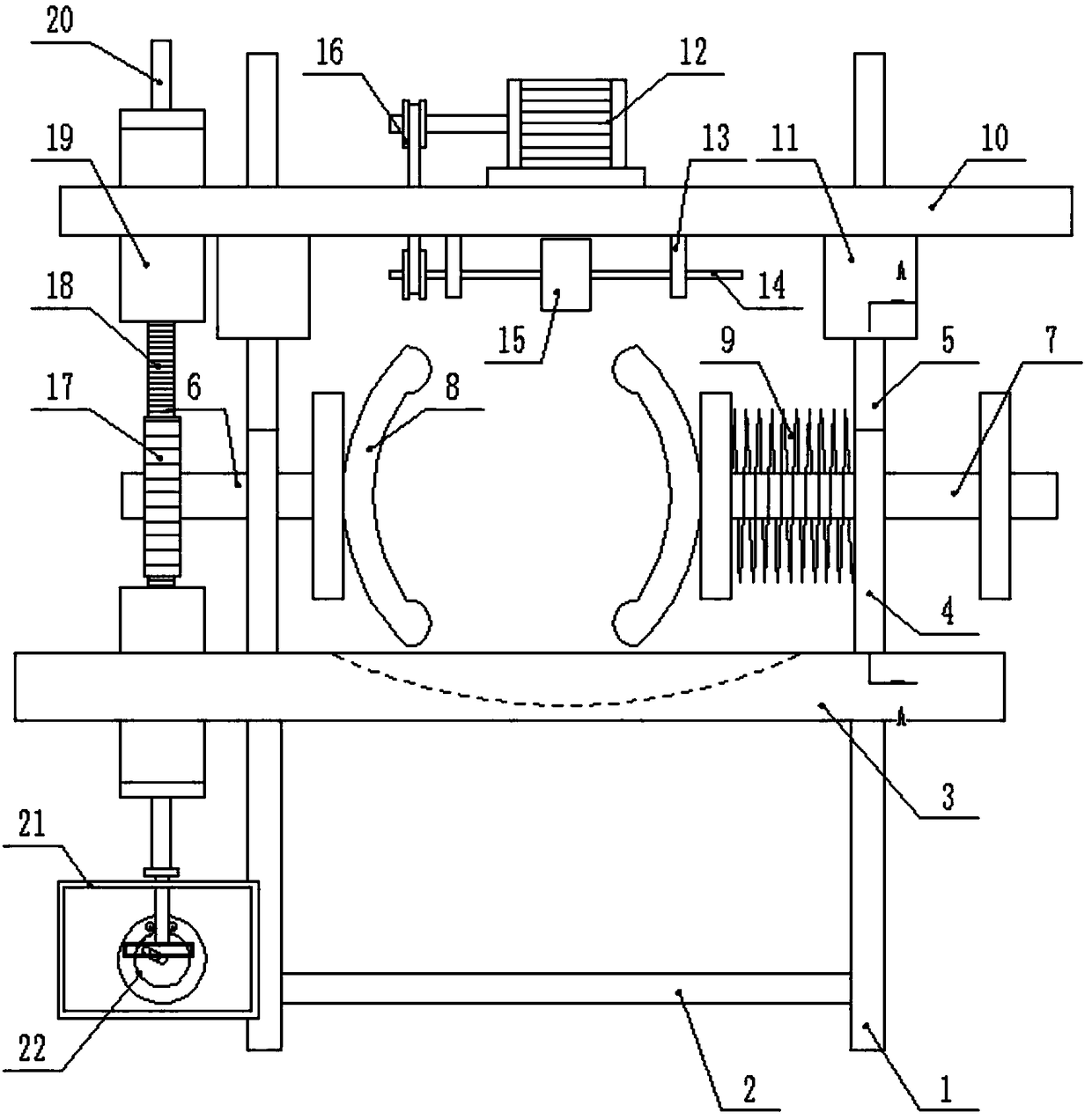
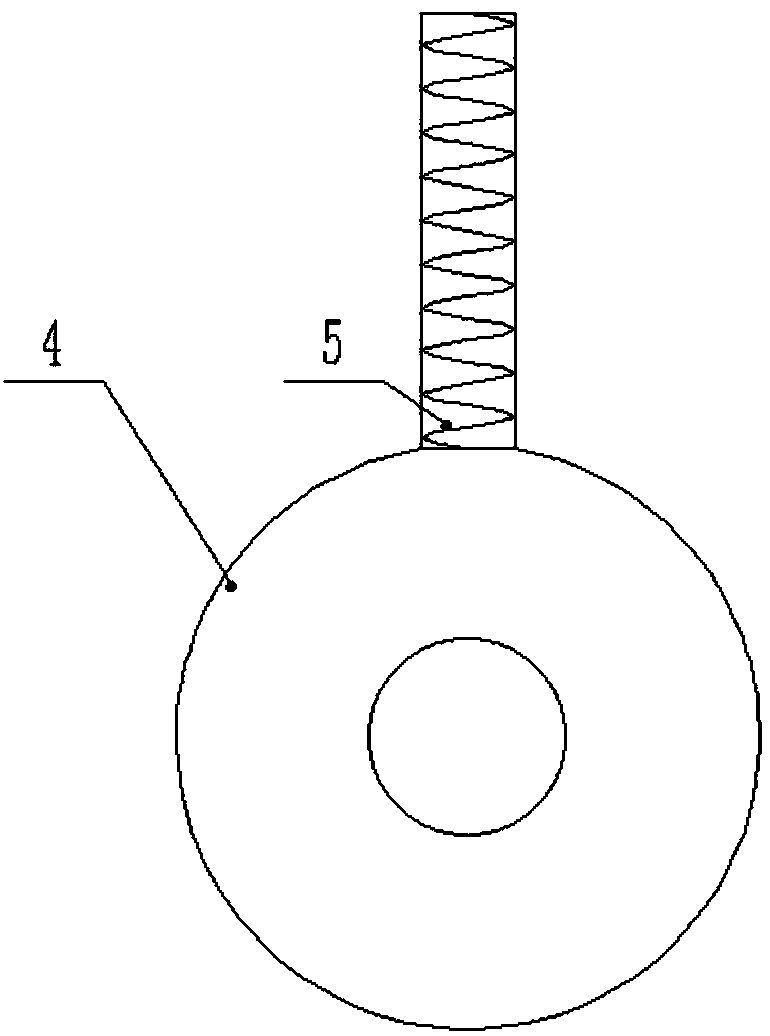
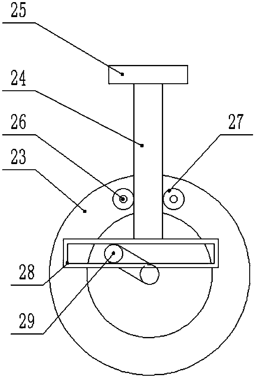
[0019] see Figure 1-3 , a polishing device for the joint of a spherical sound box shell with a disc sliding structure, including a device body, the device body is provided with a support frame 1, and a support beam 2 is arranged on the support frame 1, and the support beam 2 and the support frame 1 They are fixedly connected by welding, the top of the support frame 1 is provided with a support plate 3, and the support plate 3 is welded with the support frame 1, and the top of the support plate 3 is provided with a fixed frame 4. The frame 4 and the support plate 3 are fixedly connected by screws, the top of the fixed frame 4 is provided with a threaded column 5, and the threaded column 5 and the fixed frame 4 are integrally formed, and the fixed frame 4 is provided with a Turning lever A6 and turning lever B7, described turning lever A6 is arrang...


PUM


Abstract

The invention discloses a spherical loudspeaker box shell joint polishing device of a disc sliding type structure. The spherical loudspeaker box shell joint polishing device comprises a device body, supporting frames are arranged on the device body, a supporting plate is arranged at the tops of the supporting frames, fixing frames are arranged on the supporting plate, threaded columns are arrangedat the tops of the fixing frames, a rotating rod A and a rotating rod B are arranged on the fixing frames, the device body is provided with a supporting top plate, a polishing motor is arranged on the supporting top plate, a driven gear is arranged at the end part, arranged at the outer side of the left fixing frame, of the rotating rod A, the device body is provided with a power box, and a powerassembly is arranged in the power box. The spherical loudspeaker box shell joint polishing device has the advantages that the structure is simple, through the circulating type vertical movement, a spherical loudspeaker box shell clamped in clamping plates is driven to rotate, so that a joint of the spherical loudspeaker box shell can be effectively processed, protruding burrs can be avoided, in addition, through a circulation type power structure, the effect of polishing the joint of the spherical loudspeaker box shell can be guaranteed, the processing effect can be better, the use is convenient, and the practicability is high.

Description

technical field [0001] The invention relates to the field of sound box production, in particular to a polishing device for the joint of a spherical sound box shell with a disc sliding structure. Background technique [0002] A speaker refers to a device that converts an audio signal into sound. In layman's terms, it refers to the built-in power amplifier in the main box of the speaker or the subwoofer box. After the audio signal is amplified, the sound is played back by the speaker itself to make the sound louder. The speaker is the terminal of the entire audio system, and its function is to convert audio power into corresponding sound energy and radiate it into the space. It is an extremely important part of the audio system, responsible for the task of converting electrical signals into acoustic signals for human ears to listen directly to. [0003] The shape of the speaker is square, spherical and irregular. The speaker is generally an injection molded part. After the i...

Claims


Application Information

Patent Timeline
Patent Type & Authority Applications(China)
IPC IPC(8): B24B19/00
CPCB24B19/00
Inventor 丁剡军
Owner 嵊州市格瑞特电子有限公司
Learn More