
Method for testing and loading wafer cassettes

A wafer box and crystal-carrying technology, which is applied in semiconductor/solid-state device testing/measurement, electrical components, circuits, etc., can solve problems such as time waste, achieve the effect of improving production efficiency and ensuring test continuity

Inactive Publication Date: 2018-09-07
SINO IC TECH
View PDF2 Cites 0 Cited by
  • Summary
  • Abstract
  • Description
  • Claims
  • Application Information

AI Technical Summary

Problems solved by technology

[0006] The present invention aims at the waste of time caused by changing the wafer box in the current method of sending the wafer box into the probe station for testing, and the problem that the wafer box may need to be changed continuously when arranging retesting, and proposes a test loading wafer Cassette method ensures uninterrupted testing and saves time wasted by changing wafer cassettes

Method used


Image

  • Method for testing and loading wafer cassettes
  • Method for testing and loading wafer cassettes
  • Method for testing and loading wafer cassettes

Examples


Embodiment Construction

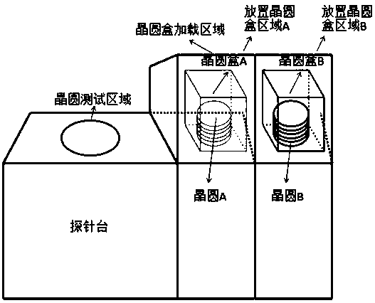
[0014] image 3 It is a schematic diagram of the structure of the wafer cassette probe station loaded in the present invention. The probe station has a special area for placing the wafer cassette, which is increased from one storage area to two storage areas A and B, and the two wafer cassettes A and B are respectively placed on the Wafer cassette rest area A and wafer cassette rest area B are to be tested; if the probe station selects wafer cassette A to test first, as shown in 4, the schematic diagram of the probe station testing wafer cassette A, under wafer cassette A After sinking into the test area for testing, the wafer box B still stays in the wafer box shelving area B. When all the wafers in the wafer box A are tested, the wafer box A is put back to the wafer box shelving area A , load the wafer box B placed in the wafer box rest area B to the test area, such as Figure 5 The schematic diagram of the probe station testing the wafer box B is shown. When the wafer box ...


PUM


Abstract

The invention relates to a method for testing and loading wafer cassettes. Two wafer cassette arrangement regions of a probe station are adopted, and therefore, when wafers in one wafer cassette are tested, the other wafer cassette can be replaced, and the wafer cassette which is being tested will not be affected; the wafer cassette which has been tested can be arranged on the arrangement region for some time, the wafer cassette can be directly loaded once the wafer cassette is required to be re-tested, and therefore, replacement time can be saved; and uninterrupted testing can be realized, the consistency of testing is guaranteed, and production efficiency can be improved.

Description

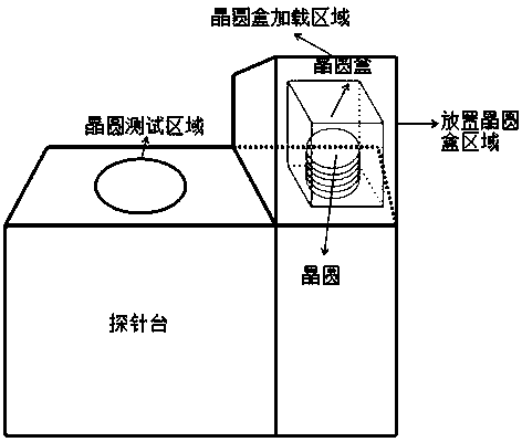
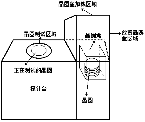
technical field [0001] The invention relates to a wafer testing technology, in particular to a method for testing and loading a wafer box. Background technique [0002] Wafer: A silicon wafer used in the manufacture of silicon semiconductor integrated circuits, due to its circular shape. Probe station: the equipment that completes the automatic movement of the wafer in the wafer test, and is connected with the test machine and the workstation to form a test system. Wafer box: a box for placing wafers, up to 25 wafers can be placed. Retest: After the wafer test is completed, test the failed die on the wafer again to avoid die failure due to abnormal test. [0003] figure 1 The schematic diagram of the structure of the existing probe station when the wafer is placed is shown. The wafer box is located in the area where the wafer box is placed and is in a state to be tested; figure 2 It is a schematic diagram of the structure of the existing probe station when testing wafer...

Claims


Application Information

Patent Timeline
Patent Type & Authority Applications(China)
IPC IPC(8): H01L21/66
CPCH01L22/20
Inventor 王玉龙凌俭波王锦汤雪飞吴勇佳
Owner SINO IC TECH
Learn More